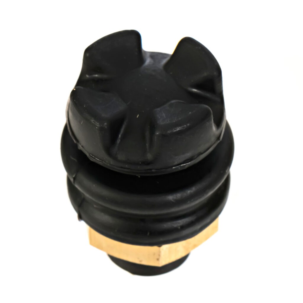
Is this the world’s smallest industrial 2-axis Hall Effect joystick?


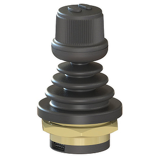
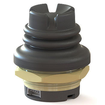
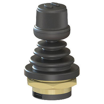
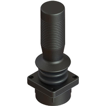
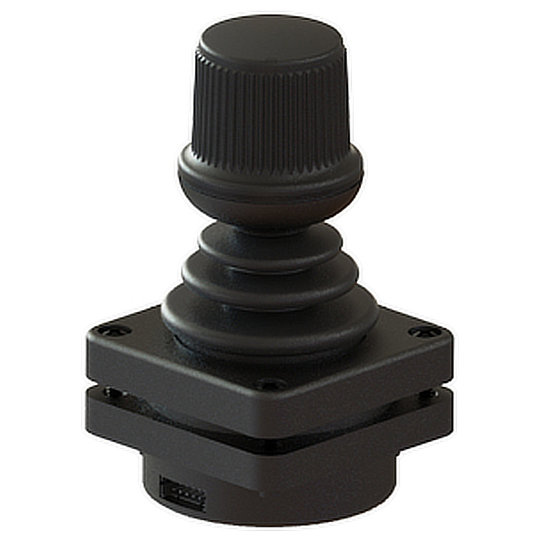
Live Electronics, the specialist distributor of rugged industrial electronics products, has introduced what the company believes is the world’s smallest 2-axis Hall Effect joystick.  Measuring just 17.5mm high above panel x 18mm in diameter, the new TS2 joystick is an IP67, analogue self-centring device, which is designed for use with remotely operated equipment, robotics and automation systems, drones and CCTV controllers.  
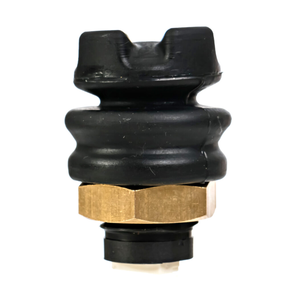
TS2

The TS2 joystick is based on proven Hall Effect technology, providing accurate, easy to control 12-bit resolution in both the X and Y axes.  The joystick offers excellent tactile feedback and has been engineered for a minimum of 2.5 million actuations.  It can be supplied with either two open or two gated limiters, a choice of circular convex or concave, castle or flat singleaxis (Y) style caps, and fits a standard 12.6mm panel cut-out with the option of a control-grip mount. 

Read more about The Hall Effect here

The new joystick is rated for a supply voltage of 5V and is available with pre-wired JST 28AWG cable or potted terminations.  Operating temperature is between -40 to +85°C, while the TS2 complies with EN61000 electromagnetic compatibility and SAE J1455 vibration and shock testing standards. 

The TS2 is manufactured in California by Ruffy Controls and is part of the company’s extensive range of industrial miniature and fingertip joysticks and switches.  Live Electronics is the company’s specialised industrial distributor in the UK.  
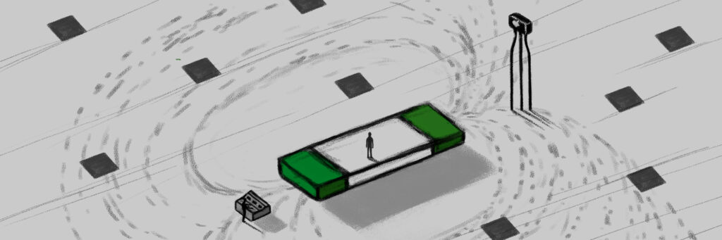
What is a linear position sensor?

What is a linear position sensor?

They are all around us – in our car suspension systems as we drive over speed bumps, in the trains we sit in as they move around curved tracks and in the ‘fly-by-wire’ aircraft that adjust their ailerons and elevators as they start to descend. They are in the factory machines that we work with every day to package and manufacture products, and in medical equipment that keeps us alive. What are these inconspicuous but crucial devices? They are linear position sensors which are helping to embed digital technologies in the next industrial revolution.

Linear position sensors and custom electronic circuitry

Linear position sensors measure the linear distance between an object and a point of reference, as well as speed and changes in position. They do this by converting linear displacement into an extra low voltage, in either an analog or digital signal. That electrical output is generated by exploiting different phenomena in nature such as magnetic fields, solar energy and electrical resistance. Excitation circuitry in the sensor creates a stimulus and signal conditioning circuitry then selects and amplifies the electrical response. Sensors then digitise the signal using an Analogue-to-Digital Converter (ADC), the digital result is then passed to a Central Processing Unit (CPU).

The Fourth Industrial Revolution

The Fourth Industrial Revolution or Industry 4.0 is well underway and adopting next generation linear position sensors that employ Application Specific Integrated Circuits (ASICs) to deliver the speed, accuracy and cost savings to industrial automation. Linear position sensors detect the location of machinery and equipment parts so they can be tracked and automated. They provide a digital signal via Ethernet connectivity to accurately report the target position in real-time with sufficient resolution. Sensor electronics are a key part of the evolution in automation, having direct influence on speed, accuracy and overall form factor.

What are the basic types of linear position sensor?

Linear position sensors consist primarily of two types: contact and non-contact, depending on whether they require physical contact to measure. Contact sensors tend to wear or degrade over time due to the constant friction for example of the wiper in a linear potentiometer measuring electrical resistance. In contrast, noncontact sensors use magnetic fields, solar energy and lasers to sense changes in position so they are less prone to wear and tear and can tolerate higher levels of vibration.

Linear encoders

A linear encoder is a sensor, transducer or readhead combined with a scale that encodes position. The sensor moves along the scale which it ‘sees’ using optical, magnetic, inductive, capacitive or eddy current technologies. It then converts the encoded position into an analog or digital signal, which is then decoded into position by a digital readout (DRO) or motion controller.

A linear encoder can be either incremental or absolute. What does this mean? Incremental encoders use a simpler method of determining movement by counting the number of pulses and then using that number to compute the position. With an absolute encoder, the output signal generated by the device creates a unique set of digital bits that correspond to a specific position of the object being measured. So incremental encoders measure the relative movement against some point of reference, whereas absolute encoders measure the position directly using a unique signal code that precisely reflects the position.

Linear encoders are used in two main areas of application: measurement and motion systems.

Measurement applications include coordinate-measuring machines (CMM), laser scanners, callipers, gear measurement, tension testers, and digital readouts (DROs).

Servo controlled motion systems provide accurate, high-speed movement in robotics, machine tools, pick-and-place PCB assembly equipment, semiconductors handling and test equipment, wire bonders, printers and digital presses. Humans design these intricate circuit boards but cannot match the speed and accuracy of robots and assembly equipment.

Linear potentiometers

In a linear potentiometer a wiper moves along a resistor as the equipment moves through the full length of stroke, providing a variable resistance related directly to position. Signal conditioners then convert this reading into other electrical output levels. Linear potentiometers are a tried and tested sensing method that are simple, inexpensive, and easy to work with. Although they are a fundamental method for detecting equipment position, as a physical device subject to constant mechanical wear they deteriorate over time and need to be replaced. They may not be resistant to liquids and contaminants, and the form factor must be large enough to accommodate the fully extended and retracted rod stroke, which can be limited in use due to installation space constraints.

Linear potentiometers can measure spring travel in bicycles and motorcycles so as to determine the optimal spring fork for challenging terrains, especially in motorsports. Imagine a mountain biker in Utah, USA speeding through wooded forests, Aspen Pine lands, bubbling streams and then across open prairie land, bouncing easily off paths covered with roots and stones thanks to the valuable data these sensors provide in the design of mountain bikes.

Aside from sport, more mundane but crucial applications include agricultural machinery, increasingly automated, moving across vast open fields. Lumbering combine harvesters use linear potentiometers for the wheel angle measurement in their steering systems as they move back and forth.

Linear potentiometers can also measure the stroke movement of both hydraulic and pneumatic cylinders by installing them directly inside the cylinder itself. The sensor compares the target stroke with the actual stroke to ensure process safety. Reliable measurement data is collected even at high pressure.

Being one of the most versatile and widely used sensors in industry, linear potentiometers are used in a whole range of applications including the control of motors and actuators, robotics, industrial machines, audio equipment volume control, automotive engine control systems, calibration for precision test equipment and medical equipment.

Hall effect sensors

A Hall effect sensor detects the presence and magnitude of a magnetic field using the Hall effect: namely when a conductor flowing with electrical current is plunged into a perpendicular magnetic field a voltage (the Hall voltage) is generated. It was discovered by the American physicist Edwin Hall in 1879. The output voltage of a Hall sensor is directly proportional to the strength of the magnetic field. Exploiting Hall Effect technology enables the sensors to be non-contact resulting in highly precise measurements and an exceptionally long mechanical life.

Hall sensors are used in proximity sensing, positioning, speed detection, and current sensing applications. Combined with threshold detection a Hall Effect Sensor can act as a binary switch. Frequently seen in industrial applications such as pneumatic cylinders, they are also used in consumer equipment for example detecting missing paper and open covers in computer printers. They can also measure filament thickness in the 3D printers as used in rapid prototyping, among other things.

Hall sensors time the speed of wheels and shafts in internal combustion engine ignition timing, tachometers and anti-lock braking systems and detect the position of the permanent magnet in brushless DC electric motors.

How can Live Electronics support manufacturers with linear position sensors?

Here at Live Electronics we are continually looking for the best products at the best price to help with modern technologies such as linear position sensors. Our linear position sensors from ZF use Hall Effect technology which allows the sensors to be non-contact resulting in highly precise measurements and an exceptionally long mechanical life.

FAQ's

What is a linear position sensor?

Linear position sensors measure the linear distance between an object and a point of reference, as well as changes in position. They are used for detecting the location of machinery and equipment parts so they can be tracked and automated.

How does a linear position sensor work?

Linear position sensors exploit different phenomena in nature such as magnetic fields, solar energy and electrical resistance to convert the displacement of moving machinery into an electrical output.

How many types of linear position sensors are there?

There are many types of linear position sensor, however the linear potentiometer is widespread being an inexpensive and easy to use piece of equipment. The Hall effect sensor however is becoming the most common due to its non-contact nature, resulting in highly precise measurements and an exceptionally long mechanical life.

How do you test a linear position sensor?

A linear potentiometer can be tested using a voltmeter. With a linear potentiometer fully extended, the voltmeter should display the maximum volts of the sensor in DC. With the linear potentiometer fully retracted, the voltmeter should display zero volts DC. The Hall effect sensor can be tested in a similar way in that the voltage changes from 0V to 5V (the high voltage can be changed based on the set up but usually this is between 1-5V, with 5V being the most common)

The Complete Guide to Joysticks – Live Electronics

In this month’s complete guide to joysticks, we are going to be discussing different types of joysticks, their history, how they work, what they are used for and their benefits.

The first confirmed use of such a device was in 1908 by the French aviation pioneer Louis Bleriot in his Bleriot VIII experimental aircraft. The device used by Louis Bleriot was purely mechanical. The first joystick as we know it today was invented at the U.S. Naval Research Laboratory by C. B. Mirick and patented in 1926. It was a two-axis electronic joystick and was originally designed for remotely piloting aircraft.

In 1944 German scientists utilised a 2-axis design to control their Henschel Hs 293 glide bombs and unpowered Fritz-X missiles. These joysticks used electrical on-off signals allowing for a more effortless radio control transmitter system. This allowed certain bomber aircraft to accurately guide both rocket-propelled and unpowered guided missiles onto their targets.

Joystick technology continued to develop gradually throughout the 50’s, 60’s and 70’s and was used in NASA’s Apollo programme, most notably in the Apollo lunar lander test models. However, their use changed dramatically in the early 1980’s when home gaming machine popularity was increasing, the first joystick-controlled gaming controller was for the Atari 5200 in 1982.

The idea of using joysticks for gaming began to gain traction with the first thumb style joystick being used in 1988 with the release of the NES MAX. The NES MAX showed how useable and intuitive joysticks could be in gaming, but it was not until the release of Sony’s PlayStation Analog joystick in 1996 that the gaming joystick really took off due to its ability to work so well within a 3D world.

Outside of gaming, the joystick found its home not only in aviation applications but also in controlling machines such as UAV’s and sub-sea remotely operated vehicles (ROV’s), construction equipment, off-road vehicles, surveillance cameras, wheelchairs, and multiple military applications.

Industrial joysticks

Industrial joysticks are widely used to control, steer, and position a wide range of heavy-duty equipment, machines, and systems such as agricultural machinery, cranes, oil rigs, forklifts, excavators, military equipment, and others. There are different types of industrial joysticks including small precision joysticks like the thumb joystick and finger joystick up to fully customised hand grips. The different types feature different actuator options, mounting styles, and controller specifications like number of axes, spring return, friction hold, and different protocol support. Industrial joysticks are also extremely robust and can withstand harsher environments. Live Electronics work with Ruffy Controls and Ultra MSI who both manufacture a wide range of high-quality industrial joysticks designed for various applications which we will discuss further throughout this blog.

Ruffy TS1 Joystick

Thumb joysticks

Thumb controllers are low-profile based joysticks that provide precise control with a variety of mounting and actuator options for ease of integration. Ultra MSI manufacture the 462 series and Ruffy Controls manufacture the TS1 series that are both perfect joysticks for applications such as Cursor Control, Target Acquisition, Security Cameras, Robotics and Automated Surgical Equipment.

Ruffy HE1 Joystick

Finger joysticks

Finger joysticks are mainly used to provide control of movement and speed in low-profile units such as wheelchairs, medical instruments, robotic operations, and applications where precision and compact size are needed and the HE1 series from Ruffy Controls is just that, offering high precision within a compact panel mounted design.

Ruffy SG Joystick

Hand Grip joysticks

Hand grip joysticks are widely used in heavy-duty applications such as mobile cranes, forklift vehicles, construction machinery, robotic machines, and agricultural equipment. Thanks to their sophisticated wear-free hall effect sensors and control mechanisms, these types of joysticks are highly versatile in multiple applications as is the SG series from Ruffy Controls which is a hall effect hand grip joystick with a redundant sensor, providing an extra level of safety making it the perfect choice for applications such as Remotely Operated Equipment and Automation Systems.

How do joysticks work?

A joystick is an input device consisting of a stick that pivots on a base and reports its angle and direction to the device it is controlling. It detects the direction of the stick by use of an electronic switch, Hall Effect, strain gauge or potentiometers.

What is a joystick?

A joystick is an input device which transforms mechanical movement from an operator and turns this into an electrical output and can control a computer game or machinery.

What are the types of joysticks?

There are several types of joysticks that most of us may be familiar with as they are used on game consoles and gaming computers, but the industrial joystick types are, thumb joysticks, finger Joysticks and handgrip joysticks.

What are joysticks used for?

Joysticks are widely used to control, steer, and position a wide range of heavy-duty equipment, machines, and systems such as agricultural machinery, cranes, oil rigs, forklifts, large vehicles, excavators, military equipment, hoist devices. Other joysticks such as small precision joysticks are used to control security cameras, remotely operated equipment and automation systems.

What is a hall effect joystick?

A hall effect joystick works in the same way to any other joystick but utilises the Hall Effect principle which allows the joystick to have a very long mechanical life due to there being no physical contact with the sensor and they can be designed to withstand excessive shock and vibration.

How does a potentiometer work?

In a joystick, a potentiometer is connected to each axis shafts so that pivoting the shaft rotates the contact arm. When the stick is moved there is a corresponding resistance change within the potentiometer. This adjusts the voltage, which can be interpreted by a computer programme as movement.

What is a strain gauge used for?

A strain gauge’s primary use is to measure force or strain. The resistance of a strain gauge changes when force is applied, and this change will give a different electrical output.

Contact our sales team today to discuss your joystick requirements. Contact Us

The Hall Effect: Explained

Introduction to Hall Effect

In this blog we are going to discuss the science of Hall Effect, how it works, why the effect is important, what products the effect is used in and what the advantages are.

What is the Hall Effect?

Hall Effect is named after American physicist Edwin H. Hall who first introduced the theory to the world in 1879 when he was doctoral candidate at Johns Hopkins University in Baltimore. Hall discovered that when a conductor or semiconductor with current flowing in one direction was introduced to a perpendicular magnetic field a voltage could be measured at right angles to the current path, this measurable voltage is the Hall Effect.

How does it work?

The Hall Effect takes place when you set current flowing through a conductor which is a material such as copper or silver that permits electrons to flow freely across the entire surface area. The electrons begin to flow in a straight line from one side of the conductor to the other. If you were to then introduce a magnetic field near the conductor, it would disturb the flow of the electrons due to the force applied. This is called Lorentz Force, which is the force on a charged particle due to electric and magnetic fields.

The magnet’s north pole pulls the negative electrons to one side of the conductor and deflects the positive electrons to the other side of the conductor. If you then put a voltage tester between the two sides you will be given a voltage reading because there is current between the positive and negative electrons, by retrieving this measurable voltage you are putting the Hall Effect principle into practice. In a semiconductor such as silicon or germanium, the drift velocity of electrons is a lot quicker due to the material used. This results in a stronger Hall Effect which corresponds to a larger voltage reading being detected and therefore a more precise reading taken.

Hall Effect Products

Hall Effect is used in several different products such as sensors, joysticks and switches. We will now discuss the different products to understand what they are, their benefits and their applications. At Live Electronics we work with several manufacturers that produce Hall Effect products, we will also discuss the different manufacturers and their products.

ZF, Speed and Direction Sensor

Hall Effect Sensors

A Hall Effect sensor is a device to measure the magnitude of a magnetic field. Its output voltage is directly proportional to the magnetic field strength through it. Hall Effect sensors are used for proximity sensing, positioning, speed detection, and current sensing applications. Other sensors include the Inductive sensor which is a non-contact electronic proximity sensor. It is used for positioning and detection of metal objects.

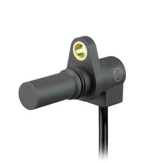
Live Electronics work with ZF Electronics who manufacture Hall Effect sensor such as the SD74/SD84/SDB4 series of Gear-tooth speed and direction sensors that are designed with two internal hall effect cells, together they can be used to detect both the speed and direction of movement of a gear. By using two Hall Effect magnetic field cells placed near to the gear-teeth of the gear that is to be measured, the movement of the gear tooth passing the magnets disrupts the magnetic field. This disruption is picked up by the sensor and the output signal can be used to calculate the gear’s speed and direction of movement. The SD74/SD84/SDB4 series has several benefits which include being IP67 rated, immune to vibration, shock, and dirt for improved functional safety. The ideal applications are Automation Systems, Conveyors and Wind Turbines.

ZF, LIN Sensor

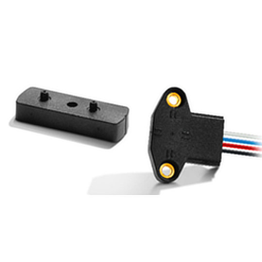
ZF Electronics also provide Linear Positions Sensors. Their LIN series are contactless hall effect sensors offering linear voltage output and a long mechanical life. The sensor has dual independent outputs with redundancy to offer the most reliable and accurate sensor possible. The benefits of the LIN series include being IP68 rated, robust and reliable. The LIN series is designed for many applications such as gear selection, hydraulic controls and steering wheel positioning.

Hall Effect Joysticks

Hall Effect joysticks are devices that use non-contact sensors to change the physical movement from an operator into an electrical signal which can be understood by a computer system. Hall Effect joysticks are extremely robust and have a very long mechanical life due to there being no psychical contact with the sensor. A Hall Effect joysticks mechanical life can range from 1 million cycles (also known as actuations) to 15 million cycles.

There are several types of joysticks being used today, one of them being the Potentiometer joystick. The Potentiometer joystick is a device that has been around for years and they contain several components that increase or decrease the level of resistance within the electronic circuit. Potentiometer joysticks do still offer great performance but in terms of long-term durability these joysticks may be susceptible to reliability issues due to the wearing of moving parts and minor vulnerability to electromagnetic interference or radio frequency interference. As mentioned previously, Hall Effect joysticks have a very long mechanical life due to there being no physical contact with the sensor and they are designed to withstand excessive shock or vibration giving them an advantage over the Potentiometer joystick.

Live Electronics work with a joystick manufacturer, Ruffy Controls. They have a large portfolio of joysticks, several of them being Hall Effect. The HE3 series from Ruffy Controls is a Hall Effect joystick that is designed with built in redundant sensors to provide an extra level of safety. Ruffy Controls joysticks can be designed specifically to meet customer needs and the HE3 series is no different. The HE3 series are available in 2 or 3 axis, provide options for push buttons on the joystick handle, a choice of limiters (square, guided feel, round limiter), the output voltage you require and they are available in different colours. The benefits of the HE3 series include being IP67 rated, extremely rugged, a mechanical life of 5 million actuations in all directions and excellent return to value. The HE3 series are the perfect joysticks for applications such as industrial machinery, agricultural machinery, CCTV control systems and automation systems.

Ruffy, Ruffy Controls, HE3 Joystick

Hall Effect Switches

Hall Effect switches are devices that turn on in the presence of a magnetic field and turn off when the magnet is removed. They are designed with contactless sensing to ensure maximum ruggedness, reliability and mechanical life.

There are several different style switches available one of them being a pushbutton switch. A pushbutton switch requires downward pressure to be applied to activate or deactivate a circuit. They provide an on-off functionality, but different variants are available. Their switching action can be maintained (staying in one position after pressure has been applied) or momentary (returning to their original position once pressure is removed). Due to electromechanical Pushbuttons requiring physical pressure to be applied to function, they experience a lot of physical wear and tear resulting in a shorter mechanical life of around 50 thousand cycles. Physical contact is largely reduced with a Hall Effect switch due to them having contactless sensing, which gives them a much longer mechanical life of around 1 million to 15 million cycles.

Elma, Multi Rotary Switch, Hall Effect, Coded Switch, Incremental Encoder Switch

Hall Effect Rotary Switches

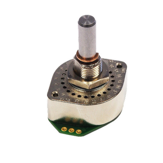
We work with Elma Electronics Ltd who manufacture the X4 series which is a high-performance Hall Effect multi rotary switch. A rotary switch is a switch operated by rotation. They are often chosen when more than 2 positions are required. The X4 series from Elma is an extremely robust and rugged switch with a mechanical life cycle of 1 million rotations. It provides an IP67 rating with a stainless-steel shaft making the switch robust and rugged. There are many applications the X4 series can be used in and examples are construction, transportation controls, machine tools and plant construction.

Advantages of Hall Effect

Hall Effect devices have many advantages, they are immune to dust, dirt and water and due to their frictionless operation, they have extremely long mechanical lives. They are robust, rugged and can withstand intense vibration and shock. Hall Effect devices can offer high speed operation and they can operate in a wide temperature range.

FAQ's

What is Hall Effect?

Hall Effect principle is when a current is passed in one direction through a conductor and a magnetic force is introduced perpendicular to this, the magnetic field moves the electronics within the conductor creating a voltage change. You can then measure the change in voltage by taking a voltage reading at right angles to the currents path, this measurable voltage is the Hall Effect.

What is a Hall Effect sensor?

A Hall Effect sensor is a device that measures the magnitude of a magnetic field. Its output voltage is directly proportional to the magnetic field strength through it.

What is a Hall Effect joystick?

Hall Effect joysticks are devices that use non-contact sensors to change the physical movement from an operator into an electrical signal which can be understood by a computer system.

What causes Hall Effect?

The Hall Effect is the movement of electrons through a conductor towards a magnetic attraction. It causes a measurable voltage differential across the conductor such that one side is positively charged and the other negatively.

What is the use of a Hall Effect sensor?

Hall Effect sensors are used for proximity sensing, positioning, speed detection, and current sensing.

How accurate are Hall Effect sensors?

Hall Effect sensors can achieve output error as low as 1%.

Contact our sales team today to discuss your requirements! Contact us