A Guide to Indicator Terminology

Introduction to Indicators

In this blog, we are going to examine the different terminology that can be used when looking at indicator lights. This will hopefully give you the language relevant to ensure you purchase the correct indictor for your needs, however, our sales team is also on hand if you have any specific requirements or questions.


What is an indicator?

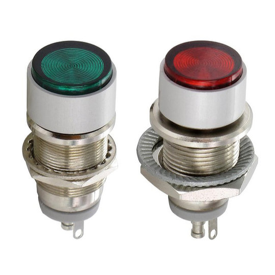
Indicator lights are visual aids that are used to relay information to a user or operator of a device. These can be large stacks of lights made up of different colours which emit a constant or flashing light to indicate if a machine is operating or if there is a fault. Alternatively, they can be smaller LED indicators designed to show when a certain function is activated or multiple indicators can be used to relay more in-depth information. The majority of indicators are now becoming LED (light-emitting diode) based as this allows for more efficient lighting to be used while also reducing the footprint of the indicator. To learn more about LEDs you can read our in-depth blog article here.

Glossary of Terms

Alternating Current (AC)

Alternating Current is an electrical current that reverses its direction within a particular frequency and is the type of current most often found in homes and businesses.


Ampere (A)

An Ampere often shortened to Amp is the international standard of measurement of the electromagnetic force between conductors, this is more often referred to as the current. An easier way to visualise this is through the river analogy is that the amperes relate to the volume of water (electrons) been moved. The higher the amperage the larger the volume of water that is moving.


Bi-Colour

Bi-colour simply means two colours. In relation to LED indicators, this means two different colours will be housed within the same body.


Binning

Binning refers to the grouping of LEDs during the production process into groups of the same colour temperature. This means the different LEDs within an LED strip or in multiple indicators will have the same colour consistency.


Candela (cd)

A Candela is a measurement of the amount of light which is emitted by a light source in one particular direction. A more in-depth explanation is that candela is the luminous intensity in a single direction from a light source that emits monochromatic ration at a frequency of 540×1012 hertz and has a radiant intensity of 1/683 watt per square radian.


Colour Rendering Index (CRI)

The Colour Rendering Index is a measurement of how accurate the colour given by a light source is when compared with the same colour in sunlight. The CRI is measured on a scale of 0-100, with 100 being an identical match, and is found mainly on LED indicators and LED strips. A CRI of 80+ is generally accepted as the standard although some LED’s are now capable of CRI’s in excess of 90.


Colour Temperature

The colour temperature of a light source is a way to describe the appearance of the light in terms of its colour. The temperature is measured in degrees Kelvin (K) with midday sunlight being around 5600°K. Higher Kelvin gives off a bluer, cooler light with extremely high Kelvin being ultraviolet. Whereas, lower Kelvin gives off a more yellow or warm light with the lowest numbers becoming red and then infrared light.


Direct Current (DC)

Unlike Alternating Current, Direct Current flows in a single direction and is used to power many smaller appliances. Direct Current also flows easily through semiconductors which is why it is used in LED indicators.


Flat indicators

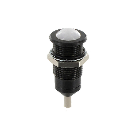
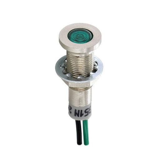
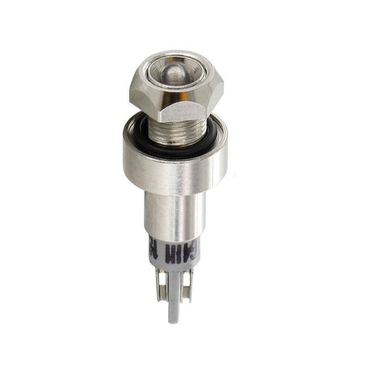
A flat indicator is a style of LED indicator that has a flat bezel with a flat or domed lens. This style of LED indicator is ideal for areas that are required to be wiped down regularly or products that require a smoother finish.


Ingress Protection (IP)

Ingress protection often shortened to IP is an international standard for how protected a product is against solid objects and moisture. The first number after the IP relates to its solid protection while the second number refers to its liquid protection. To learn more about IP ratings you can read our blog article here.


Industrial Indicator Lights

Industrial indicator lights are generally larger style light units that are specifically designed to work within the industrial sector. These can be single lights or lighting towers which can produce continuous or flashing lights in different colours.


Light Emitting Diode (LED)

A Light Emitting Diode is a semiconductor that converts the electrical energy placed upon it into visible light through the release of photons. Read our blog article to understand more about LEDs and how they work.


Lumens (lm)

A lumen is a measurement of the total brightness of a light source as perceived by the human eye. Lumens, therefore, give you a simpler way to determine the brightness of a light when compared to other methods such as Watts, which were primarily used for incandescent lights. The higher the lumen rating the brighter the light appears.


Luminous efficacy

Luminous efficacy is a measurement of how efficient an LED strip or LED indicator is. This is calculated by dividing the number of lumens the light source emits by the number of Watts it uses.


Milliampere (mA)

A milliampere or milliamp is one-thousandth of an ampere, therefore 1000 milliamperes equals 1 ampere.


Millicandela (mcd)

Millicandela is one-thousandth of a candela, therefore 1000 millicandela equals 1 candela.


Panel Mount

Panel Mount describes how the indicator is mounted. These are designed to be fitted to an external case or enclosure with the wiring terminations on the inside and the LED and bezel on the outside.


Plastic indicators

Plastic indicators are manufactured with fully plastic housings, this makes them lighter and usually slightly cheaper than their metal housing alternatives.


Reflector indicators

Reflector indicators are specially designed with a bezel that can direct the emitted light into a focused point. This means they are generally brighter and therefore ideal for areas with high levels of ambient light.


RGB

RGB stands for Red, Green and Blue. RGB LEDs are designed so that all 3 individual LEDs are within a single housing. They are also individually adjustable which allows an RGB LED to produce over 16 million colours.


Solid-state indicator

A solid-state indicator relates to an LED style indicator rather than an incandescent style. This is because an LED does not have any electrical elements which are separate from the main system such as the filaments in incandescent bulbs.


Viewing Angle

The viewing angle of a LED refers to the size of the cone of light that is emitted up to the point where it loses half of its peak illumination level. A viewing angle of 20° for instance will be a much narrower light than one with a viewing angle of 72°.


Voltage (V)

Voltage or Volts is the difference in electric potential between two given points. An easier way to visualise this is the river analogy where the voltage relates to the steepness of the river or the speed of the water (electrons). The higher the voltage the faster the water is moving.


Watt

A watt is the standard unit of measurement equivalent to one joule per second. It is more commonly referred to as the power rating of the device or circuit. To calculate the watts of an electrical system you multiply the voltage by the ampere e.g. 240V x 2A = 480 watts.


Waterproof LED indicators

A waterproof LED indictor is usually a submersible or semi-submersible indictor, these usually have an IP rating of IP67 or IP68 and are ideal for applications where the LED indicator will be subjected to environments with high moisture content or the possibility of being submerged.

FAQs

What is an indicator light?

Indicator lights are visual aids that are used to relay information to a user or operator of a device.

What is an LED indicator?

An LED indicator is a type of indicator light that incorporates a light-emitting diode. This results in a highly effective light source that has low power consumption and a long lifespan.

What are the uses of an indicator light?

Indicator lights are used to relay information to an operator, these are extremely useful in applications such as industrial & commercial control panels, agricultural equipment, marine & military applications and medical & scientific equipment.

Why do some LED indicators have resistors?

Some LED indicators are available with built-in resistors, these are called ballast resistors and are used to limit the amount of current which flows through the LED. This is a safety feature that is useful in some but not all circumstances to prevent the LED from being destroyed by electrical overload.

What is a flat indicator?

A flat indicator is a style of LED indicator that has a flat bezel with a flat or domed lens. This style of LED indicator is ideal for areas that are required to be wiped down regularly or products that require a smoother finish.

What is an LED Strip?

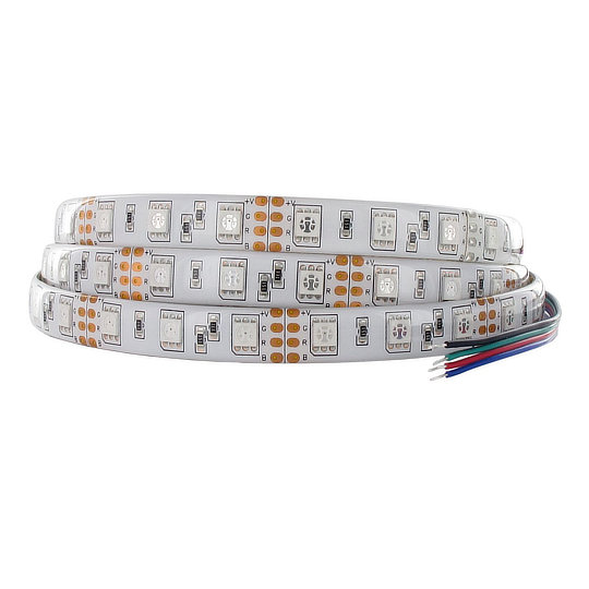
An LED strip is a length of surface-mounted LEDs often fitted to a flexible base. This allows the lighting to be designed in different ways including custom lengths and even lighting over or around curves, which would not be possible with conventional lighting such as incandescent bulbs.

What is an IP rating?

An IP rating is an international standard of how protected a product is against solid objects and moisture. Read our blog article to learn more about IP ratings.

What IP rating is waterproof?

While products that are rated IP65 and upwards are suitable for outdoor use, only products rated IP68 and IP69K can be considered fully waterproof as these are submersible in water for prolonged periods of time. IP67 rated products can also be fully submerged in water but these are usually only tested for 30 minutes in water up to 1m in depth.

Contact our sales team today to discuss your requirements! Contact Us
The Hall Effect: Explained

Introduction to Hall Effect

In this blog we are going to discuss the science of Hall Effect, how it works, why the effect is important, what products the effect is used in and what the advantages are.

What is the Hall Effect?

Hall Effect is named after American physicist Edwin H. Hall who first introduced the theory to the world in 1879 when he was doctoral candidate at Johns Hopkins University in Baltimore. Hall discovered that when a conductor or semiconductor with current flowing in one direction was introduced to a perpendicular magnetic field a voltage could be measured at right angles to the current path, this measurable voltage is the Hall Effect.

How does it work?

The Hall Effect takes place when you set current flowing through a conductor which is a material such as copper or silver that permits electrons to flow freely across the entire surface area. The electrons begin to flow in a straight line from one side of the conductor to the other. If you were to then introduce a magnetic field near the conductor, it would disturb the flow of the electrons due to the force applied. This is called Lorentz Force, which is the force on a charged particle due to electric and magnetic fields.

The magnet’s north pole pulls the negative electrons to one side of the conductor and deflects the positive electrons to the other side of the conductor. If you then put a voltage tester between the two sides you will be given a voltage reading because there is current between the positive and negative electrons, by retrieving this measurable voltage you are putting the Hall Effect principle into practice. In a semiconductor such as silicon or germanium, the drift velocity of electrons is a lot quicker due to the material used. This results in a stronger Hall Effect which corresponds to a larger voltage reading being detected and therefore a more precise reading taken.

Hall Effect Products

Hall Effect is used in several different products such as sensors, joysticks and switches. We will now discuss the different products to understand what they are, their benefits and their applications. At Live Electronics we work with several manufacturers that produce Hall Effect products, we will also discuss the different manufacturers and their products.

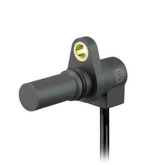
ZF, Speed and Direction Sensor

Hall Effect Sensors

A Hall Effect sensor is a device to measure the magnitude of a magnetic field. Its output voltage is directly proportional to the magnetic field strength through it. Hall Effect sensors are used for proximity sensing, positioning, speed detection, and current sensing applications. Other sensors include the Inductive sensor which is a non-contact electronic proximity sensor. It is used for positioning and detection of metal objects.

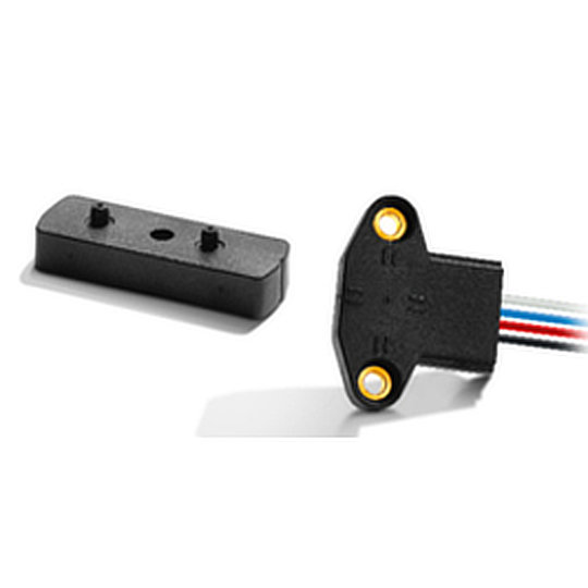
Live Electronics work with ZF Electronics who manufacture Hall Effect sensor such as the SD74/SD84/SDB4 series of Gear-tooth speed and direction sensors that are designed with two internal hall effect cells, together they can be used to detect both the speed and direction of movement of a gear. By using two Hall Effect magnetic field cells placed near to the gear-teeth of the gear that is to be measured, the movement of the gear tooth passing the magnets disrupts the magnetic field. This disruption is picked up by the sensor and the output signal can be used to calculate the gear’s speed and direction of movement. The SD74/SD84/SDB4 series has several benefits which include being IP67 rated, immune to vibration, shock, and dirt for improved functional safety. The ideal applications are Automation Systems, Conveyors and Wind Turbines.

ZF, LIN Sensor

ZF Electronics also provide Linear Positions Sensors. Their LIN series are contactless hall effect sensors offering linear voltage output and a long mechanical life. The sensor has dual independent outputs with redundancy to offer the most reliable and accurate sensor possible. The benefits of the LIN series include being IP68 rated, robust and reliable. The LIN series is designed for many applications such as gear selection, hydraulic controls and steering wheel positioning.

Hall Effect Joysticks

Hall Effect joysticks are devices that use non-contact sensors to change the physical movement from an operator into an electrical signal which can be understood by a computer system. Hall Effect joysticks are extremely robust and have a very long mechanical life due to there being no psychical contact with the sensor. A Hall Effect joysticks mechanical life can range from 1 million cycles (also known as actuations) to 15 million cycles.

There are several types of joysticks being used today, one of them being the Potentiometer joystick. The Potentiometer joystick is a device that has been around for years and they contain several components that increase or decrease the level of resistance within the electronic circuit. Potentiometer joysticks do still offer great performance but in terms of long-term durability these joysticks may be susceptible to reliability issues due to the wearing of moving parts and minor vulnerability to electromagnetic interference or radio frequency interference. As mentioned previously, Hall Effect joysticks have a very long mechanical life due to there being no physical contact with the sensor and they are designed to withstand excessive shock or vibration giving them an advantage over the Potentiometer joystick.

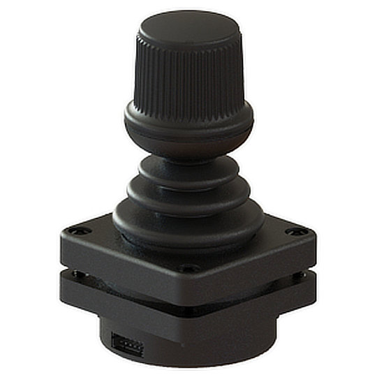
Live Electronics work with a joystick manufacturer, Ruffy Controls. They have a large portfolio of joysticks, several of them being Hall Effect. The HE3 series from Ruffy Controls is a Hall Effect joystick that is designed with built in redundant sensors to provide an extra level of safety. Ruffy Controls joysticks can be designed specifically to meet customer needs and the HE3 series is no different. The HE3 series are available in 2 or 3 axis, provide options for push buttons on the joystick handle, a choice of limiters (square, guided feel, round limiter), the output voltage you require and they are available in different colours. The benefits of the HE3 series include being IP67 rated, extremely rugged, a mechanical life of 5 million actuations in all directions and excellent return to value. The HE3 series are the perfect joysticks for applications such as industrial machinery, agricultural machinery, CCTV control systems and automation systems.

Ruffy, Ruffy Controls, HE3 Joystick

Hall Effect Switches

Hall Effect switches are devices that turn on in the presence of a magnetic field and turn off when the magnet is removed. They are designed with contactless sensing to ensure maximum ruggedness, reliability and mechanical life.

There are several different style switches available one of them being a pushbutton switch. A pushbutton switch requires downward pressure to be applied to activate or deactivate a circuit. They provide an on-off functionality, but different variants are available. Their switching action can be maintained (staying in one position after pressure has been applied) or momentary (returning to their original position once pressure is removed). Due to electromechanical Pushbuttons requiring physical pressure to be applied to function, they experience a lot of physical wear and tear resulting in a shorter mechanical life of around 50 thousand cycles. Physical contact is largely reduced with a Hall Effect switch due to them having contactless sensing, which gives them a much longer mechanical life of around 1 million to 15 million cycles.

Elma, Multi Rotary Switch, Hall Effect, Coded Switch, Incremental Encoder Switch

Hall Effect Rotary Switches

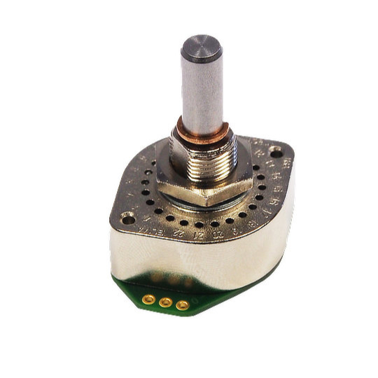
We work with Elma Electronics Ltd who manufacture the X4 series which is a high-performance Hall Effect multi rotary switch. A rotary switch is a switch operated by rotation. They are often chosen when more than 2 positions are required. The X4 series from Elma is an extremely robust and rugged switch with a mechanical life cycle of 1 million rotations. It provides an IP67 rating with a stainless-steel shaft making the switch robust and rugged. There are many applications the X4 series can be used in and examples are construction, transportation controls, machine tools and plant construction.

Advantages of Hall Effect

Hall Effect devices have many advantages, they are immune to dust, dirt and water and due to their frictionless operation, they have extremely long mechanical lives. They are robust, rugged and can withstand intense vibration and shock. Hall Effect devices can offer high speed operation and they can operate in a wide temperature range.

FAQ's

What is Hall Effect?

Hall Effect principle is when a current is passed in one direction through a conductor and a magnetic force is introduced perpendicular to this, the magnetic field moves the electronics within the conductor creating a voltage change. You can then measure the change in voltage by taking a voltage reading at right angles to the currents path, this measurable voltage is the Hall Effect.

What is a Hall Effect sensor?

A Hall Effect sensor is a device that measures the magnitude of a magnetic field. Its output voltage is directly proportional to the magnetic field strength through it.

What is a Hall Effect joystick?

Hall Effect joysticks are devices that use non-contact sensors to change the physical movement from an operator into an electrical signal which can be understood by a computer system.

What causes Hall Effect?

The Hall Effect is the movement of electrons through a conductor towards a magnetic attraction. It causes a measurable voltage differential across the conductor such that one side is positively charged and the other negatively.

What is the use of a Hall Effect sensor?

Hall Effect sensors are used for proximity sensing, positioning, speed detection, and current sensing.

How accurate are Hall Effect sensors?

Hall Effect sensors can achieve output error as low as 1%.

Contact our sales team today to discuss your requirements! Contact us

IDEC S3 Connect Push-In Technology

How much is your time worth?

As the saying goes time is money! So it makes sense that reducing time spent on monotonous jobs such as panel installations can only be a good thing, this is where IDEC’s S3 connect range comes in to play. The S3 connect range, standing for safe, simple and smart, is IDEC’s Push-In terminal technology which covers their E-stops, safety interlocks, CW, YW and HW switches, safety relays and relay sockets.

The benefit of the S3 technology is multifaceted, firstly the time-saving aspect of allowing solid conductors, wire-end ferrules or stranded cable to be simply pushed into the connection saving an estimated 55% on installation time when compared with screw terminations. As someone who spent many hours standing in front of industrial panels with crimpers and a screwdriver, I know how much of a benefit this would have been!.

Secondly is the safety aspect of the S3 system, the push-in terminations guarantee optimal contact security so loose or overtightened connections are no longer an issue. The constant pressure of the termination also makes these the ideal solution for areas with high levels of vibration, which can be found within certain industries and applications.

Thirdly, the high visibility terminal numbering system and design of the IDEC products makes them ideal for reducing space taken up with cable management and allowing for more accurate and quicker troubleshooting when faults occur. Lastly, if any issues were found, the S3 range makes it extremely quick and easy to modify or replace components.

To see more about how the S3 range from IDEC can save you time they have created a video showing the comparison between the S3 system and standard screw terminations, which can be viewed below.

If you have any questions or would like more information on the IDEC S3 system please contact our sales team and we would be more than happy to help.

What is an LED and How do they Work?

Introduction to LED Lights

What Does LED Stand for?

LED stands for Light Emitting Diode. To break this down further a diode is a semiconductor that will allow current to flow in one direction while restricting the movement of current in the opposite. For reference a semiconductor is a material that will pass electricity not as easily as a conductor such as copper wire does, but better than an insulator such as plastic. As a byproduct of a diode under electrical current photons are produced and by altering the semiconductor materials these photons escape at different wavelengths which we can see as different coloured light being emitted.

History of the LED

The concept of electroluminescence, producing light from electricity, is at the heart of LED technology. An English engineer called Henry Joseph Round was the first person to report light emissions from a diode in 1907, this light was too faint for any real-world applications but it was the beginning of the LED we know today.

In 1920 this phenomenon was replicated by Bernhard Gudden and Robert Wichard Pohl, but it was not until 1927 when Russian scientist Oleg Losev began to properly study light emitting from solid-state diodes and published his theories.

The actual term electroluminescence was published for the first time in a report on light being produced by Zinc Sulphide powder when an electric current was passed through it by George Destriau in 1936. This was followed shortly afterwards in 1939 when Hungarian physicists Zoltán Bay and György Szigeti took out a U.S. Patent demonstrating that visible light-emitting diodes were possible.

It was not until 1952 however that this phenomenon of light-emitting diodes was finally explained by Professor Kurt Lehovec following his research into Oleg Losev’s theories. This opened the way for other researchers to take these findings further primarily in relation to the materials they used. In 1955 Rubin Braustein reported that Gallium Arsenide diodes could emit infrared light when electrified. Following further research Rubin and his partner, Egon Loebner patented a Lead Antimonide and Germanium alloy which could emit green light in 1958.

In 1962 a scientist working for GE called Nick Holonyak Jr invented the first red light diode on the visible spectrum which opened up the first commercial use of LEDs in the 60’s with IBM first using these LEDs for an early computer in 1964 followed by Hewlett Packard incorporating the LEDs into its calculators in 1968.

With one of the main components used within these LEDs being Gallium Nitride crystals a reliable and easy source would be required to ensure LEDs could become a more viable option. This led to researchers Herbert Maruska and James Tietjen developing a way to grow Gallium Nitride crystals and publishing a paper outlining their methods in 1969.

In 1971 the first blue LED was created by Jacques Pankove and Edward Miller by using Zinc doped Gallium Nitride, however much like the first record of light emissions in 1907 this blue light was not bright enough for any useful applications. This was followed in 1972 by the creation of the first yellow LED by an electrical engineer M. George Craford who used a red and a green Gallium Phosphide chip. Craford then went on with fellow researchers Walden C. Rhines and Herbert Maruska to successfully created a blue LED using Magnesium doped Gallium Nitride rather than Zinc doped. This Magnesium doped variant, although still offering very low light, set the standard for the development of future blue LEDs.

Shortly after in 1976 the first high brightness and efficient LED was created by Tom Pearsall; this LED was bright enough to open the way for higher quality optical fibre communications.

Throughout all this time only single colour and non-white LEDs had been possible due to the elusiveness of a high brightness blue LED. So, starting in 1986 physicists Isamu Akasaki and Hiroshi Amano worked on developing a high-quality Gallium Nitride that would be required for a blue LED. In 1993 an electrical engineer called Shuji Nakamura with the assistance of Akasaki and Amano managed to create the first high brightness blue LED which quickly led to the development of white LEDs through the utilisation of red, green and blue LEDs in a single unit.

By 2002, white LEDs were commercially available however extremely expensive at around £90 per bulb. Even so with their long life, and lower power consumption many public buildings began to make the change to LED lights, with them becoming much more common in the early 2000’s. By 2020 LEDs had become one of the main sources of light with prices coming down and people swapping out their old halogen and florescent bulbs at home for energy-efficient LED bulbs. With the focus on environmentally friendly, low cost and highly efficient lighting being ever more prevalent it is highly likely that LEDs will be the primary light source going into the future.

LED Anatomy

How do LEDs work?

There are two main factors that allow an LED to work. First is the diode, which is an electrical component comprising of two terminals that only allows electricity to flow in one direction. One key point here is that all diodes release photos, however not all diodes emit light. The second factor allowing an LED to work is the type of semiconductor material used, the changing of these materials is what allows the photons to be seen in different colours due to the wavelengths at which they are emitted.

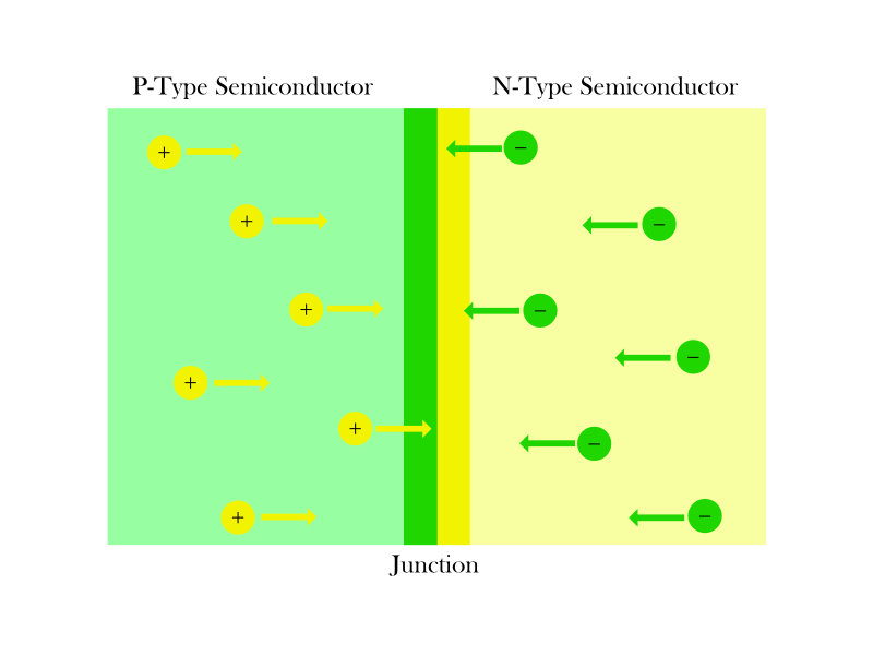
A diode is made up of two layers of semiconductor materials sandwiched together. These two semiconductors are called the p-type and n-type. The p-type semiconductor creates electron deficiencies when a current is passed through it, thereby the atoms within the materials lose weakly bound electrons, this is sometimes referred to as the p-type layer having holes. The atoms within the n-type semiconductor however have an excess of electronics.

LED Semiconductor Anatomy

When in an electrified state the electronics in the N-Type semiconductor and the holes in the P-Type semiconductor rush towards to the junction, this exchange of electrons releases photons which we see as light.

Due to the electron holes in the p-type layer and the excess in the n-type layer, when the diode is in an un-electrified state the electrons in the n-type side flow into the p-type side. The effect of this movement leads to the n-type side having a positive charge and the p-type side a negative charge. This is what prevents an external current from flowing in the wrong direction, if an incorrectly attached current were increased however then at a certain point this would be enough to break the bonds causing the diode to blow. When an electrical current is passed through the diode it is said to have a forward bias, this means the current is moving from the positive terminal connected to the p-type layer and into the negative terminal connected n-type layer. When an electrical current is passed through the diode the current forces the atoms in both the p-type and n-type sides to move towards the junction area, the area where the two sides meet. This increases the exchange of electronics from the n-type side to the p-type side which significantly increases the number of photons released.

By using certain materials such as Gallium, Aluminium and Indium the wavelength at which these photons travel out of the diode can be adjusted which results in visible light of different colours being produced. It has also been discovered that most of the light produced by the diode comes from the junction contact nearer the p-type region, due to this LEDs are designed so that this area is kept close to the surface ensuring the maximum amount of light is transmitted.

How do LED Lights change colour?

It is important to note that LED’s do not change their colour, LEDs are however available in a variety of colour wavelengths from unseen light such as ultraviolet and infrared through the entire spectrum of human colour vision.

As mentioned previously this change in colour is due to the use of different materials. For instance, Aluminium Gallium Nitride gives out ultraviolet light, Indium Gallium Nitride creates a blue/violet light, Silicon Carbide a blue, Gallium Phosphide a green, Gallium Arsenide Phosphide a yellow/orange and Aluminium Gallium Indium Phosphide a red light. There are also many different variations that produce lighter or darker variations of these colours.

Due to the range of colours available this means that by mixing two or three different diodes in a single housing it is possible to get many more colour variations. It also means that by mixing red, green, and blue the first white LEDs could be produced. Recently, a new way to manufacture white LEDs has been created, by utilising a blue LED with a short wavelength of around 450 to 470 nanometres combined with a phosphor material, yellow light is created. This yellow light when mixed with the remaining blue light results in white light being created. This is more cost-effective to manufacture than using 3 different diodes and reduces the amount of energy required.

LEDs can also be controlled by microcontrollers which can change the current delivered to individual diodes within a mixed diode LED or light strip. These are predominantly RGB, red, green, and blue but can also incorporate a white diode for an RGBW LED or strip. By individually adjusting the different currents on an RGB light it is possible to create up to 256 different shades of each colour resulting in 16.7 million colour combinations.

Types of LED

When you google LEDs, you will notice that there are a few different types of LEDs available, one thing to remember here is that internally they are all identical. That being said the external variations available allow for LEDs to be used in many different applications. The styles most people will be aware of are the LED replacements for home lighting with bayonet, screw, or GU pins for connecting to an existing light system. However, there are many more types used in commercial and industrial applications.

The most commonly seen LED light you will find are through-hole LEDs which usually come in a standard 3mm or 5mm diameter. These have two long pins and a domed top which can be clear or coloured. These can be used for breadboard circuits when learning about electronics or creating new projects or within products as indicator lights. The other main style seen is the SMD or surface mount device LED, these are flat LEDs that can be fitted to PCB or into lengths to create LED strips, which we will discuss later.

The majority of LEDs sold by Live Electronics Ltd are manufactured by Sloan AG and IDEC, these are indicator lights, also known as pilot lights, illumination units and LED strips. Indicator lights are designed to relay information to an operator of a product this could be through a warning light, machine is running light or any other information which will need to be visually seen. Illumination units are pre-built lighting units that are larger and are designed to illuminate a work area or instrument panel whereas, LED strips are flexible lighting systems similar to illumination units.

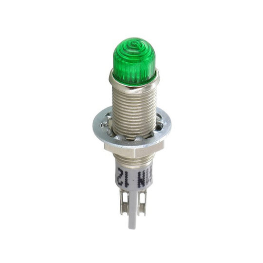
The types of indicator LEDs we supply are coloured cap indicators, flat indicators, front exchangeable indicators, reflector indicators and plastic indicators. A coloured cap indicator is simply a housing with different styles of bezel and different coloured caps over the LED. The different coloured cap means that an operator can see immediately the colour of the light even if the LED is turned off.

Sloan, Sloan AG, 114 Series, LED Indicator
Sloan, Sloan AG, 183, 184, 188 Series, LED Indicator

The next types of indicators which are commonly used are flat indicators and reflector indicators. The difference between these is that the flat indicators have a flat bezel with either a flat or domed lens whereas a reflector indicator usually, but not always, has a higher shaped bezel that reflects the light in a certain way. Both styles are available in similar housings and colours but are used in different ways. A flat indicator is useful when machines are required to be wiped down regularly or products require a smoother finish, these can also be RGB allowing for a larger variety of colours to be used. A reflector indicator however is used more in areas where light needs to be focused on a certain point or a much brighter light is required such as for use in areas with high ambient light levels.

Sloan, Sloan AG, 876, 877, 886, 887 Series, LED Indicator

Another type of LED which can be very useful within industrial environments are front exchangeable indicators. These are comprised of a mounting socket which is fitted to the equipment and will accept a matching LED. The LEDs come with both the LED and lens in a single unit, this allows for a broken LED or an LED with broken lens to be quickly replaced without having to dismantle the equipment to do so, saving costly downtime to the machines. Another option available is a fully plastic indicator these tend to be cheaper, lighter, and slightly larger than their metal counterparts as such these are seen a lot in industrial applications such as control panels.

The final type of LED product Live Electronics Ltd offer are LED strips, as mentioned above these use SMD LEDs which are combined into a single length of flexible LED lights. These can be unprotected or protected by being covered in a layer of silicone with some being IP68 rated for underwater use. These types of strips are available in single colours, RGB or RGBW making them ideal for interior design applications, high-end products, TV and Film and custom projects. Due to the flexible nature and the use of RGB LEDs and microcontrollers LED strips are being found in more and more applications where aesthetics are a major selling point.

Sloan, FPL-RGB, LED Strip

Advantages of LED Lights

The main reason you hear people changing to LED lights from previous forms of lighting is their longer lifespan and efficiency. Whilst it is true that LEDs are efficient with some claiming to be up to 90% more efficient over incandescent bulbs, due mainly to incandescent bulbs producing 90% heat and 10% light compared to modern LEDs offering 95% light and only 5% heat. But there are many other advantages to LED lights, as mentioned they last much longer than older technology, but they also do not contain toxic elements which can be found in older technology. In a time when global warming is a paramount concern to many people a light source which does not pollute the planet while offering a longer service life at lower energy costs is an ideal solution.

From a design and manufacturing point of view these benefits go further than the green benefits mentioned above. The energy savings allow for higher brightness bulbs to be used for the same power consumption or the ability to lower power consumption of a product and increase its battery life. LEDs are also better at focusing light meaning light is not lost in all directions and is delivered to the required area. They also produce very low amounts of heat so are not only safe for operators and consumers but can be used in areas which are temperature sensitive. They also do not emit harmful ultraviolet light which means they will not damage materials, paints or dyes making them idea for museums and art galleries, while dedicated ultraviolet LEDs are ideal for forensic and scientific use.

LEDs are also more robust and resilient than older style bulbs which makes them a great choice for equipment which is subjected to extreme environmental factors, impacts and vibrations such as off-road vehicles, agricultural equipment, marine, military, medical and scientific equipment. LED strips can also offer huge potential for designers to create incredible visual lighting designs whether this be in high end luxury vehicles, within commercial and office buildings or for TV and film.

These are the main reasons why LEDs are now chosen over other types of lighting. If you are interested in incorporating LEDs into your next design speak to a member of our sales team at sales@liveelectronicsgroup.com.

Contact our sales team today to discuss your LED requirements! Contact Us
D-Sub Connectors – All you need to know

D-Sub Connectors

The D-subminiature connector, more commonly known as a D-Sub connector is a family of connectors that were introduced by Cannon in 1952 and they are still being widely used today. Although in today’s electronic marketplace technology is ever-changing and adapting to meet consumer wants and needs. Despite being over 60 years old, there are still plenty of devices using D-Sub technology that we are still reliant on. In this article, we are going to discuss what D-subs are, where they are commonly used, what they look like and their importance in today’s modern world.

What is a D-Sub Connector?

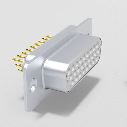
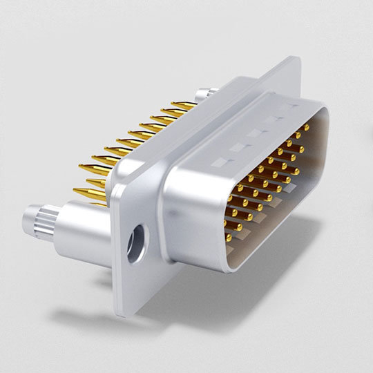
The D-sub is one of the most popular electronic connectors in the world, with many types, sizes, and applications. It is a very versatile type of electrical connector. These compact connectors take their name from their characteristic D-shaped shield. D-subs establish a connection between two points to facilitate the transfer of information or power.

D-subs were used for monitors and disk drives, now they are used for industrial and military networking, sensors and in areas where electromagnetic interference can be an issue to the device or the to the environment.

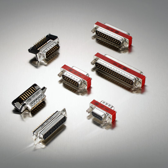
D-sub is the name given to a family of connectors, and several connectors that make up the family are Combi D-Sub Connectors, Dual-Port D-Sub Connectors, Filtered D-Sub Connectors, High-Density D-Sub Connectors, Standard D-Sub Connectors and D-Sub Hoods which will now be explained in further detail.

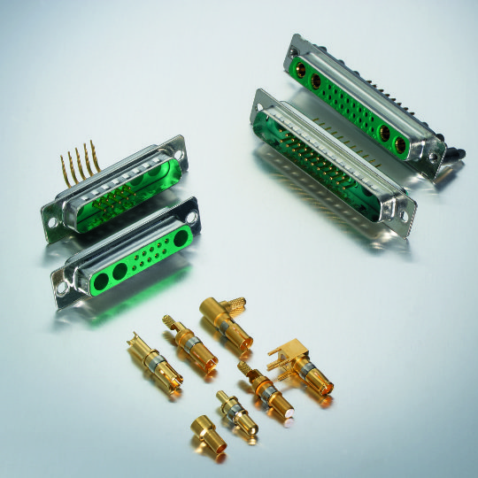
Combi D-Sub Connectors are a hybrid connector featuring different connector styles within a D-Sub housing. This allows designers the ability to have a mix of different contacts within a single D-Sub whether these be signal, high current, high voltage, coaxial or pneumatic. Deltron AG, a Swiss manufacturer of high-end D-subs have 24 standard styles to choose from each offering distinct features within 5 different housing sizes. The number of contacts range from 2-43. Terminations can be either solder pin, press-fit or solder cup. The power contacts can be 10A, 20A, 30A or 40A and can be requested with sealing up to IP68.

To understand more about IP rating please see the blog on our website which explains it in more detail here.

Dual-Port D-Sub Connectors are designed for applications that require multiple connector ports with limited “PCB” space, through the stacking of two 90° D-Sub connectors, one on top of the other. Dual Port D-Subs are available in various designs with numerous assemblies and the number contacts range from 9-37.

Deltron AG, Deltron, Filtered D-Sub Connectors, Filtered D-Subminiature, Filtered D-Sub

Filtered D-Sub Connectors have a very good filter quality to protect against Electromagnetic Interference. The Planar Filter Connectors (FP) and the PI Filter Connectors from Deltron AG are specially developed for industrial applications and offer excellent protection against Electromagnetic Interference (EMI) and Radio Frequency Interference (RFI) which can be caused by lightening, solar magnetic storms, radio signals, mobile phones, electronic motors, computers, medical equipment and power lines.

Standard D-Sub Connectors are high quality and robust connectors designed for the most demanding applications. They are available with different assembly parts for mounting, for example, crimp assembled,  press-fit assembled, solder cup assembled, or 90° angled solder pin.

Deltron AG, High-Density D-Sub, D-sub Connectors

High-Density D-Sub Connectors are designed for applications which require the best possible contact density. Due to the high density of the 15, 26, 44, 62 and 78 contacts, this series is ideal for the most modern applications. A very common high-density connector is the Video Graphics Array (VGA) connector which is a 3 row 15 pin connector used in computers.

D-Sub Hoods are designed to perfectly match Deltron AG’s range of high-quality D-Sub connectors. They are available in 9, 15, 25, 37 or 50 pin versions. The D-Sub Hoods provide optimum protection to the connector to prevent damage.

What does a D-Sub Connector look like?

They are shaped like the letter “D,” with one side slightly longer than the other. Due to the shape, there is only one way to connect a device. All D-Sub connectors have a metal housing that surrounds two or more rows of male or female contacts. Inside the housing, the contacts are aligned to match the equivalent pins or sockets in the mating half of the connector. The contacts are generally gold-plated copper alloy, and they are surrounded by a layer of insulation made from a variety of materials, including glass-filled thermoplastic, a common insulating plastic.

All the Deltron AG D-Subs discussed above have contacts that are finished in a hard gold plate over nickel and they are available in different quality classes (QC).  For example, QC1 is capable of 500 mating cycles or QC2 which is capable of 200 mating cycles.

What is a D-Sub Connector used for?

D-Subs were once heavily used in home computing, printer cables, computer game controllers, external floppy disk drives, network ports and multi-channel audio recording systems but technology has advanced the need for D-subs has decreased in these areas. As previously mentioned, they are now predominantly used in industrial, aerospace, military, transportation and medical diagnostics because they are extremely rugged, small enough to fit into tight spaces, have a very long-life cycle and can withstand being exposed to harsh environments.

Due to their ability to be created in multiple variations, be environmentally sealed & locked and have EMI filtering, D-Subs are used in many industries such as aerospace, military, industrial, transportation and medical. They are commonly used in critical applications such as helicopters, combat aircraft, high-speed rail, patient monitors, ultrasound and MRI imaging.

What are the advantages and disadvantages of a D-Sub Connector?

As modern technology is forever changing and constantly becoming more lightweight and sleeker, D-Subs are being utilised less on modern devices like laptops, monitors and televisions where physical depth and weight are important to the user. D-Sub connectors take much longer to plug in and unplug due to their size and termination, unlike USB and HDMI connectors.

The advantages of D-Sub Connectors are they are extremely rugged and can be used in harsh environments. They are small enough to fit into tight spaces and have a long-life cycle. They are diverse and work well within many different industries as we have discussed throughout. D-Subs are well suited for locking technology which means that hardware keeps the plug and socket components in the mated position, they have several different terminations e.g., solder, screw and crimp meaning they offer better resistance to tampering as well as jostling. As can be seen, the D-sub technology may not be the most up to date solution but remains the best solution in many different environments.

If there is anything we can help you with please contact us with your enquiry Contact Us

Ultimate Buying Guide for USB Connectors & Cables

In a world where most homes have a multitude of electrical devices and technology is ever-changing, it is no surprise that many of us complain that there are too many cables and wires to keep a track of.

The image of a drawer, box or cupboard filled with random electric cables is all too familiar to many of us. For many, the USB port has become a household name for electrical devices, but most people have no idea about the varieties of USB connectors and cables and the importance they bring.

In this buying guide, we hope to make sense of all the different USB connectors and cables on offer by explaining how they work, which to pick and what the difference between them all really is.

What is USB?

USB stands for “Universal Serial Bus” and was created as an industry standard for connectors and cables worldwide on electrical devices such as computers, phones, appliances, and other peripherals. Before the advent of USB, electrical manufacturers created their own power and connector cables tying consumers into purchasing their cables, chargers, and power adapters. Global adoption of USB technology meant that electrical device users could start to rely on a technology that was flexible and compatible across a wide variety of accessories and other devices.

The purpose of a USB cable is to connect to a USB port via a USB connector. The USB port is often found as part of the device and the USB cable is used to either power this device or connect/communicate with other external devices.

The universal nature of the USB port, connector and cable has meant that they have become increasingly common must-have items on modern electric devices such as printers, keyboards, cameras, video game controllers and mobile phones.

What is a USB connector?

A USB connector is the physical connecting point from a USB cable to a USB port. A USB connector allows for a stable and properly connected USB. One way it does this is by ensuring that only a specified type of USB cable can be connected to a specific USB port. Without the proper connector, there would be much higher cases of users attempting to connect the wrong cables into USB ports.

What are the different types of USB connectors and cables?

To understand the different varieties of USB cables and connectors it is important to make a distinction between “USB type” and “USB version”.

“USB type” refers to the physical nature of the connector and corresponding USB port. Differences across “types” can often be easily identified by the connectors at the end of the USB cable.

A USB Type-A connector is usually standard on most USB cables as it is designed to fit the most found port – the USB Type-A port. However, the type of USB cable will usually take the name of whichever connector is not USB Type-A found at the other end of the cable. This is where you start to notice a difference between Type-A, Type-B, Type-C, micro and mini connectors, and cables.

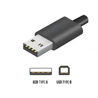
USB Type A Connector

What is USB Type-A?

  • The oldest in design and as such, the most common. USB Type-A is usually compatible from USB 1.0 upwards.
  • Most found on mobile devices, computers, laptops, and flash drives.
  • The connector is rectangular in design and can only be inserted into a USB-A port one way.
USB-A Connectors

What is USB Type-B?

  • Type-B connectors are usually used for the purpose of powering devices and as such you are more likely to find them on larger electrical items like printers or scanners.
  • The design of the Type-B connector is obvious as it takes more square shape with a wider aperture for the connectors.
USB Type C Connector

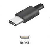
What is USB Type-C?

  • USB Type-C cables are the latest on the marketplace and are notably smaller/flatter connectors.
  • The major difference in USB Type-C cables is their ability to carry video and data at a much higher and faster level. For example, the USB-C can support data transfer speeds of up to 10 Gbps. Type-C are increasingly more common on the very latest laptops, mobile devices and charging hubs.
  • Type-C is compatible from USB 1.1 to t USB 3.2
USB-C Connectors
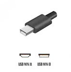
Mini USB Connector

What is Mini USB?

  • The clue is in the name! The Mini USB is a miniature connector, making it ideal for mobile/handheld devices that require smaller ports.
  • Mini USB is most found on digital cameras and camcorders.
  • Increasingly, the Mini USB has been phased out in favour of the newer Micro USB cable and port.
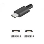
Micro USB Connector

What is Micro USB?

  • The Micro USB is an even smaller and slenderer version of the Mini USB and most found on modern smartphones, digital cameras and handheld devices like the Amazon Kindle or GPS SatNav systems.
  • The Micro USB is compatible for USB 2.0 and 3.0

What are the differences between USB versions?

One of the most asked questions is understanding the difference between USB 1.0, USB 2.0, USB 3.0, and USB 3.1. Most computer users never even notice the different version but knowing the difference is important when picking a USB cable if you want to use the cable for a specific purpose.

Power supply/charging

USB 2.0, 3.0 and 3.1 all support power supply and charging. The older USB 1.1 version does not.

Video

If you need a USB cable for supporting video data, you will need USB 3.0 or 3.1. Older 1.1 and 2.0 versions are not able to support video.

Fast data transfer

Picking the right version depends on how fast you want to transfer data. If you need to transfer high volumes of data, then you may want to opt for USB 3.0 or USB 3.1 which transfers at 5Gbps and 10Gpbs, respectively. If you only need to transfer smaller packets of data, then 2.0 may suit at 480 Mbps. USB 1.1 can still transfer data but only at a speed of 12Mbps.

Frequently Asked Questions

Does USB 3.0 connectors work with 2.0 ports?

Yes. USB 3.0 and USB 3.1 are backwards compatible. This means that they can be used on older ports. However, this will only operate at USB 2.0 speeds.

Is USB Type-C universal?

Whilst USB Type-C connectors and cables are backward compatible, it is important to understand that simply buying a newer type does not mean that you will get the results you expect. A common issue many consumers face is that they purchase a USB Type-C cable/connector with the view of using it to charge a smartphone but connect it to a USB Type-A port.

As previously mentioned above, USB Type-A ports were not specifically designed for powering many new smartphones. The best-case scenario is that you may find your new “fast charging” Type-C cable takes much longer to charge. The worst-case scenario is that using the wrong cable may damage your device.

In this case, a well-designed USB cable should reduce the risk of damage by preventing a device from drawing too much power from a Type-A port. However, there are numerous cheaper and poorly designed USB cables that do not have this prevention system that will attempt to draw too much power from the port to the connected device. This can cause damage to both the connected device and/or the device the port is contained within.

You should always check that the USB cable is compliant and compatible for the devices and ports you intend to connect it to.

How long can a USB cable be?

Expert guidance from the USB Implementers Forum suggests that cable length is based on transfer rate. The longer the cable, the slower the data transfer is likely to be as the distance it travels is longer. If the cable is too long, it may not even be able to deliver power either

The guidance states that a USB 3.1 cable (operating at about 5 Gbps) should be at the most, 2 meters. The USBIF states that a USB 3.1 cable (operating at about 10 Gbps) can reach up to about 1 meter. Slower USB cables (such as those that use USB 2.0) can be slightly longer up to 4m.

What is USB OTG?

USB OTG or “on-the-go” is a specification of USB that allows a device to obtain and transfer data without the need for a PC. USB OTG devices essentially turn the USB into the host. For example, most modern Android phones have USB OTG and allow for the smartphone to be connected to devices like printers or hard drives. To make this work however, you will need an OTG compliant cable and connector, so do check before making any expensive purchases.

Contact us today to find out more about the USB connectors we can offer Contact Us

The GT Contact Snap-In Connector

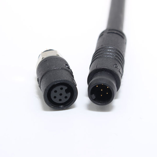
Designed to offer environmental sealing up to IP67 within a robust housing, GT Contact’s Snap-in connectors do not disappoint.

Offered in 5A 2 or 3pin (IP67) and 2A 6pin (IP65) variations, you have the choice of cable to cable or cable to panel connectors which fit cutouts of 6.1mm diameter with an outer diameter of just 8.5mm. The Snap-in series offer a snug connection which will not be accidentally disconnected, providing a perfect solution for when space is at a premium.

Find out more about the Snap-in series here.

GT Contact’s USB Type C

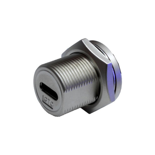
Introducing GT Contacts USB-C 3.1 connector range, the latest addition to their USB line up.

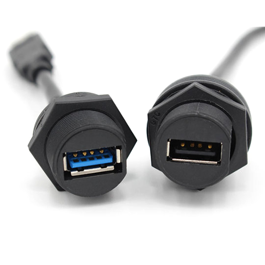
The USB-C range incorporates the ruggedness and superior build quality that is expected in all GT Contact products. Available in plastic or metal construction these connectors are sealed to IP67 and IP68 respectively. The rear potting of all panel mount connectors ensures your products are protected even when the connector is unmated.

The ruggedness of these connectors coupled with connection speeds of up to 10Gbps makes them perfect for applications where performance cannot be compromised regardless of the environment.

Find out more about the USB-C range here or contact us today.

The benefits of our custom cable assembly service

Our custom cable assembly service can help companies both large and small create the best products possible while saving on overall costs and decreasing manufacture time.

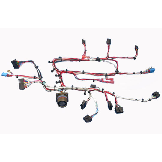
We have an ongoing partnership with a UK based cable assembly company who we have worked with for many years and who have delivered excellent products time and time again. Thanks to this partnership we are able to offer custom cable assemblies from simple cut and tinned wires through to entire wire harnesses. These can be terminated with a large variety our franchised products such as connectors, switches and LED indicators to create a drop-in cable-component solution.

The main benefits of choosing a custom cable assembly service over off the shelf cables can be broken down into 12 areas.

Design:

One of the great parts about creating a custom cable through Live Electronics Ltd is the years of design experience our partners bring. You can utilise this experience to ensure the finished product meets all the specifications you require.

Prototyping:

Prototyping of the cable assemblies is a great way to ensure the cables not only meet the theoretical specification but also work well within the products. This is not only from an electrical standpoint but also how the cable fits within the product and how easy the installation is for your engineers.

Accuracy:

The accuracy and repeatability of custom cable assemblies are hugely important. We work to ensure that all products ordered through Live Electronics Ltd are not only checked by our partner company but also prior delivery to you.

Flexibility:

Having a custom cable assembly means you have the ability to make small changes as required. This can be done for updates to the design of your product or for limited runs which offer a bespoke edge to your products.

Volumes:

We can work with you throughout the entire life cycles of your product by offering small, medium and high quantities of your customised cable(s). This means you will not have to look elsewhere if orders increase or decrease, giving you peace of mind within your supply chain.

High-Quality:

A great benefit of having a custom cable assembly created is the ability to customise all the components you require. This means you do not have to compromise on the quality of the cables or added components which may not be available with off the shelf alternatives. This also means you are able to save both time and money by not having to adapt off the shelf cables in-house to meet your expectations.

Time:

Rather than purchasing standard cables which would require changes to length and to be terminated in house. You can have a fully completed cable delivered to you ready for installation. This is especially useful if you have connectors or switches which require termination to a cable before installation.

Waste:

Along with saving time the use of custom cable assemblies also helps with the reduction of waste. Some cables are only available in large reels or standardised lengths, this means you may end up with leftover cables which are not suitable for your needs. This is not only wasted money but also in many cases can have an impact on the environment. By utilising a specialist company these parts can often be used for other projects therefore saving both the wastage of product and cost.

Cost:

Speaking about costs, custom cable assemblies can help reduce the overall cost of your completed product in two main ways. One, the cost of purchasing the products can in some cases be reduced as you do not have to buy large amounts which would not be used. Secondly, installation time can be greatly reduced by having cables that require no additional alteration and can be created as a drop-in solution.

Precise:

Custom cable assemblies offer a precise and clean finish to products. By having a cable or wiring harness which is specially designed for your application this can eliminate the need to “hide” cables or have unwanted excess cable within the products making for a cleaner looking finish. It is also possible to have the cables clipped or shrink-wrapped to keep the cables tidy and logos, company branding or serial numbers added.

Quality:

By using a specialist company you are guaranteed a high level of quality on a consistent basis. Aside from meeting your requirements time and time again, we can also have the cable assemblies 100% tested and reports created for your records. This limits any potential issues that may arise from faulty wiring saving both time and cost in servicing faulty products.

Peace of mind:

By purchasing custom cable assemblies through Live Electronics Ltd you will have a standard lead time for all your cables meaning you can better plan your production runs. We can also offer scheduled drops so you receive the products when you require them and if needed, and within reason, change these dates at very short notice.

As can be seen, the benefits of custom cable assemblies can be wide-ranging. From simply knowing the products will meet your exact specifications and be delivered on time helping planning. Through to help with cable design, the use of higher quality components, and full testing reports. Custom cable assemblies could be the ideal solution to many of your current issues.

Contact us today to discuss your projects.


A quick guide to switch terminology

Back to Basics

A switch is an electromechanical device which is used to connect or disconnect an electrical circuit without the need to remove an item from the circuit, as you would with a connector. As there are so many types of switches available a basic understanding of switch terminology can help when choosing a switch.

If you are still unsure of the best switch for your needs please feel free to contact us.

Actuator The actuator is a mechanical device that the operator uses in order to activate the switch. This could be the cap of a pushbutton or a lever on a microswitch.
Actuation Force This is the force which is required to be placed on the actuator in order for the switch to be activated or deactivated.
Alternate/Maintained Action Switch This is a switch style where once the switch has been activated the switches actuator stays in that position until it is manually changed.
Base/Housing The housing is the main body of the switch, it is a protective cover for the electrical contacts within and provides insulation for the user as well as IP protection and robustness to the switch.
Break Before Make/BBM This is a style of double-throw switch where one circuit is opened before the second circuit is closed.
Switch capacity The switch capacity is the amount of current the switch can safely operate under.
Contacts The contacts are the current-carrying parts within the switch that complete the electronic circuit. These are also the parts that open and close when the switch is operated.
Detent A detent is a physical non-locking catch within the switch that indicates an activation point has been reached and can offer an audible click and/or tactile feedback to the user.
Dielectric Strength The dielectric strength is the switches ability to withstand arcing, if a higher current is applied then arching may occur resulting in degradation to the switch contacts.
Double-Throw This is a style of switch which makes one circuit while simultaneously breaking another circuit.
IP Rating The IP rating system is a universally recognised system for describing the ingress protection against physical objects and moisture. To learn more about this check out our guide here.
Electrical Life This is the expected life of the switch when it is used under normal conditions and under its stated switching capacity.
Lever Actuator A lever actuator is a hinged piece of metal that is used to press the actuator of the switch. This is useful when a switch is automatically activated and is predominantly found on microswitches.
Make Before Break/MBB This is a style of double-throw switch where one circuit is closed before the second circuit is opened.
Momentary Action Switch This is a switch style where the circuit is made or broken only when the switch is activated. Once force is removed from the actuator the switch returns to its normal state. For instance, a normally closed switch once pressed would break the circuit, once the switch is released the circuit would be closed again.
Normally Closed/NC This is when a switches contacts are closed therefore making the circuit when the switch is not activated.
Normally Open/NO This is when a switches contacts are open therefore breaking the circuit when the switch is not activated.
Over Travel This is the distance the actuator will continue to travel once the switch contacts have been closed or opened.
Pole A pole refers to a circuit, therefore a single-pole switch can operate one circuit, a double pole switch two separate circuits and an 8 pole switch 8 separate circuits.
Pre Travel This is the distance the actuator is required to travel before the contacts are closed or opened.
Reset Point This is the point when the switch returns its normal position. i.e. If a momentary and normally open switch is closed the point at which the circuit is reopened when the actuator is being decompressed is the reset point.
Throw This refers to the number of contact points within the switch. For instance, a single throw makes or breaks a single circuit whereas a double-throw makes one circuit whilst simultaneously breaking another circuit.
Snap Action This is where the contacts within the switch snap open or closed at high speed. This is independent of the speed with which the actuator is pressed, once the actuator gets to its activation point the contacts will spring open or closed rapidly. They will then return to normal just as fast once the actuator has reached its reset point.
Wiping Action This is the lateral movement of contacts within the switch, this is a design feature seen predominantly within microswitches and helps to clean the contacts of welding.


Common Abbreviations

SPST   Single Pole Single Throw

SPDT  Single Pole Double Throw

DPST  Double Pole Single Throw

DPDT  Double Pole Double Throw


What is RFI/EMI shielding and filtered connectors?

EMI stands for Electromagnetic Interference whereas RFI relates to Radio Frequency Interference. These terms are often interchangeable with RFI actually been a subcategory of EMI, therefore, we will be discussing EMI specifically below.

First of all, what is EMI? EMI are types of energy waves with different frequencies (size of waves) which are caused by the acceleration of electron movement within an electrical device. Common manmade sources of EMI include radio signals, mobile phones, electronic motors, computers, medical equipment and power lines. There are also naturally occurring EMI sources such as lightning and solar magnetic storms. Alongside these more common sources, some sectors such as military and governments also need to be aware of sources such as a high altitude electromagnetic pulse (HEMP) from a nuclear device and other electronic warfare weapons.

Problems due to EMI are often not so dramatic as a weapon of electronic warfare. Interferes caused to the normal operation of electronic equipment could be as minor as hissing on the phone or unattractive TV hazing. It can however be extremely serious in products such as medical equipment which could give out incorrect data during surgery resulting in the death of a patient. It is therefore extremely important that electrical designers pay close attention to limiting the effects of EMI in line with the different international standards organizations.

The overall term for this is EMC or Electromagnetic compatibility. “EMC is the ability of a device, unit of equipment, or system to function satisfactorily in its electromagnetic environment without introducing intolerable electromagnetic disturbances to anything in that environment” [Reference 1].

In more basic terms this means design engineers need to produce electronic equipment which can operate normally without interference when in an environment with other electrical equipment. All the while also ensuring that EMI is not leaked from the product into the surrounding environment which could then interfere with other devices. This can be seen in everyday life with products like mobile phones which can still work when on a desk next to a laptop connected to Wi-Fi and using Bluetooth keyboard and mouse and external display. All these devices are giving on different waves of EMI and are still able to work within the boundaries they are designed for.

Usually, this protection or filtering is done through the use of physical shielding whether from a metal cover, EMI wire mesh or metal/silicone-metal paint within the enclosure. The best shielding material is highly dependent on the type of EMI frequency the device is emitting. In most designs, it is usual to have these covers as near to the emitting source as possible. This has the two beneficial functions, one making the shielding more effective and two making housing designs easier.

The main failure points within these EMI shields and enclosure is their joints due to improper gaskets being used, seams and any apertures in the design. As cable entry and exit is required in most devices limiting the EMI into or out of these particular apertures can be tricky. This is where the use of filtered connectors has an important role to play. Connectors with low pass filters built-in allow for the low-frequency currents and signals to be passed unhindered. At the same time, the high-frequency signal waves related to EMI are attenuated, meaning the signal strength in the system is reduced or in some instances stopped completely.

A filtered D-sub for instance is a component that has been designed to reduce high-frequency interference from EMI. The simplest way to achieve this is through the C or feed-through filter which incorporates a single capacitor placed between the ground and the signal line of the contacts. This then acts as a low pass filter meaning that any interference from inside a product is not released out into the surrounding environment and/or any external interference is not transferred to the inside of the product.

You can view our range of filtered D-sub connectors here.

A quick guide to connector terminology

Connectors may be very basic components that many people do not give much thought to. However, there are now so many different styles of connector it can be useful to know some of the terminology used. This can not only help navigate the different connectors on offer but also help you identify the best connector for the job.

Back to basics

A connector is an electromechanical device used for joining two electrical parts, usually, this would be connecting a cable to a system or cable to another cable within an electrical circuit. There are many different types of connectors which can achieve this and knowing the general terminology can go a long way to choosing the correct style of connector for your requirements.

Male The male part of a connector is called the plug, this generally includes the pin contacts for the connection.
Female The female part of the connector is called the socket, this generally holds the contact sockets where the male pins insert to create the connection. The female side is commonly the live side of the connection as the contact sockets are more difficult to touch making the connection safer.
Jack Some connectors may also be referred to as a jack, this is the female part of a connection that is installed on the surface on an encloser. Common jack connections are RJ45 (ethernet), telephone and audio (RCA) jack connectors.
Jack Plug The male part of a jack connection is still a plug and is often called a jack plug to differentiate it with other plug connections.
Inline/Cable An inline or cable connection describes a connector used to connect one cable to another. These are usually in a straight line but can also be 90° connectors.
Chassis/Panel A panel-mounted connector is one that is designed to be installed onto a panel or enclosure. These are available in different mounting options and are a secure way of bringing wiring into a product.
PCB Mount As the name suggests these are connectors where the socket is soldered directly onto a PCB board.


Splice/Butt Connectors These connectors permanently join two wires or cables together, they are usually smaller than standard connectors do to their non-mating design.
Circular Connectors These are a very standard style of connector with many different options. They have a circular shell which means they can utilise many different mating styles. They can also be produced with high levels of waterproofing and higher robustness compared to other styles of connector.
Hybrid Connectors These connectors can safely carry a mix of both power and signal circuits so are ideal for saving space or mitigating potential wiring issues. Hybrid connectors can also carry a mix of electronic and non-electronic circuits such as a signal circuit mixed with a pneumatic or optical signal circuit.


IP Rating The IP rating system is a universally recognised system for describing the ingress protection against physical objects and moisture. To learn more about this check out our guide here.
Filter Connector A filtered connector is specially designed to allow signals to pass through uninterrupted while limiting the amount of EMI (electromagnetic interference) entering or exiting the product. To find out more about EMI check out our guide here.


Pins/Contacts The pin or contact of a connector refers to the metal pins inside which make the electrical connection and complete the circuit.
Pin/Contact Number This is the number of electrical contacts within the connector.
Pin/Connector Size This is the diameter of the electrical contact within the connector. This also directly relates to the amount of current the connector can handle.
Pin Layout/Contact Arrangement This relates to the design of the electrical contacts including the spacing between the contacts and their layout. This means other connectors even with the same contact number will not fit always fit the connector as the contacts will not line up.


Shell/Backshell The shell is the body of the connector, this provides the ability to mate the connectors. It also offers the electrical insulation, EMI protection and the connectors robustness and weather sealing properties.
Shell Size This is the dimensions of the shell. The size is usually the diameter of the connector but it can also be the panel cut out size or the full dimensions of the connector depending on the manufacturer.
Keyway A keyway is designed to only allow a matching connector to mate. This is made up of one or more small protrusions with a specific placement on one side of the connection while the mating connector has cutouts of the same size and placement. This allows these connectors to fit together and reduces the chance of mating the wrong connectors.
Bayonet Coupling This is a style of mating where you push the connectors together and then part turn a locking nut which fixes the connectors together. The benefit of this is that is it a solid connection which is quicker to connect and disconnect when compared with screw style mating.
Screw Coupling This style of mating is where the connectors are pushed together and then a locking nut is screwed into position on the mating connector. This style of connector takes longer to connect but gives the most solid style of connection and can offer higher IP ratings.
Push-Pull Coupling A push-pull connector is mated together by lining up the keyway or contacts and then pushing the two connectors together until you hear and feel a positive click. To separate the connectors you push the connectors together while pulling the locking nut away from the mating connector. This releases the connection and the connectors can be pulled apart.
Snap-In Coupling This style of connector is held in place by friction. Once the keyway has been lined up you push the connector together until you hear and feel a click. To disconnect these you simply pull the connectors apart.
Magnetic Coupling Magnetic mating connectors use a magnetic force to hold the connectors together. These have the added advantage of being easily disconnected which means they are ideal for applications where a machine needs to be moved quickly or accidental damage to the connectors could occur such as in medical devices.
Plating Plating is the process of adding a thin layer of material to a different material. This can be seen on both the shell and contacts of a connector. The contacts are often made of a highly conductive metal this can then be gold plated to offer better transmission of extra-low voltage signals. The connectors shell can also be plated which can be for protection or aesthetic purposes, such as nickel plating to give a better look to the connector.
Rear Potted Rear potting is the final sealing at the back of a panel mount connector, this is done to prevent water ingress to an enclosure even if the connector itself is not covered.
O-ring An O-ring is a sealing ring that fits around the edge of a connector, this gives the connector a high amount of protection again water ingress.
Termination Style This relates to the way in which the connector contact is attached to the electronic wires of the circuit.
Crimp Crimp terminations use a crimping tool to compress the contact material onto a wire thereby holding it in place. These can be used on very small contacts and are generally quicker than soldering.
Solder Soldering is where solder wire is melted into a bucket on the contact and the wire of the electronic circuit is melted (soldered) to the contact. This offers a very strong and reliable connection but generally takes longer than crimping.
Screw This is a very basic and easy way of connecting wires to a connector. A wire is placed into a pre-made opening on a contact and a screw is then tightened to hold the wire in place. The benefit of this is the ease of installation and the ability to easily disconnect the wire in the future. Screw terminations are only available on some connectors due to the size on the contacts prohibiting their use.
Back/Rear Mounted This relates to how the connector is mounted to a panel or enclosure. With back mounting the connector is installed from behind the panel with the mounting flange sitting inside the panel and the locking nut being on the outside.


Front Mounted This relates to how the connector is mounted to a panel or enclosure. With front mounting, the connector is installed from the front of the panel with the mounting flange sitting outside of the panel and the locking nut being on the inside. This style of mounting often gives a flush finish to a panel which is useful in applications requiring cleaning or for aesthetic reasons.