Industrial Connectors: What Engineers Should Consider Beyond Pin Count

When specifying industrial connectors, it can be tempting to treat pin count as the primary selection factor. It defines how many signals or power circuits you need, so it feels like a logical starting point.

But in practice, pin count only tells part of the picture. Operating environments, mechanical demands and electrical challenges all introduce a much broader set of considerations. Getting these right at the specification stage is considerably less costly than dealing with failures once equipment is installed and in use.

Ingress Protection

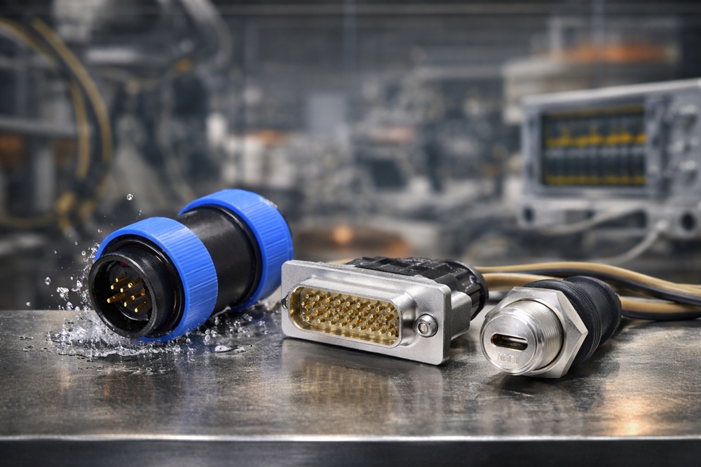
Ingress Protection (IP) is a standardised measure of how well a connector resists the entry of solid particles and liquids. The rating is expressed as two digits. The first covers protection against dust and solids, the second against water. An IP67-rated connector is fully dust-tight and can withstand temporary immersion, while IP68 extends that protection to continuous submersion.

A common mistake is selecting a connector with an adequate IP rating on paper without accounting for how it behaves when disconnected or only partially engaged. A connector’s IP rating applies in its fully connected state, meaning both halves fully plugged together and locked. In practice, connectors on maintenance access points or portable equipment that is regularly moved and reconnected may spend significant time unmated, exposing the seal to contaminants over time. Some connectors are available with protective caps for the unmated half for this exact reason, helping to preserve the seal when disconnected for extended periods.

Different connector ranges handle this in different ways. Screw-lock and bayonet-coupling circular connectors provide a secure, repeatable connection interface with consistent sealing force. This makes them well-suited to environments where vibration or accidental disengagement are concerns. Push-pull connectors, used widely in applications requiring frequent connection and disconnection, can maintain IP67 or IP68 ratings across their full connection cycle. This is a critical consideration in factory automation or outdoor instrumentation.

For applications requiring data or USB connectivity alongside environmental sealing, rugged IP67 and IP68-rated USB connectors are worth considering. These are available with USB-C options and extend the same level of protection to interfaces not originally designed with industrial environments in mind.

EMI Shielding

Deltron AG, High-Density D-Sub, D-sub Connectors

Electromagnetic interference is a persistent challenge in industrial settings. Variable speed drives, motor controllers, switching power supplies and high-current cabling can all generate significant electrical noise. For signal-level circuits running in proximity to these sources, even a well-designed cable assembly can become an antenna if the connector interface introduces a break in the shielding.

Effective EMI shielding at the connector level requires 360-degree circumferential contact between the cable shield and the connector’s metal housing. Partial or intermittent contact significantly reduces shielding effectiveness. In circular connector designs, the metallic shell itself contributes to this shielding, which is one of the reasons circular connectors remain a preferred choice in demanding EMI environments. The circular design provides a continuous conductive enclosure around the connection point.
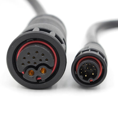
GTC, GT Contact, Hybrid Connectors, Power and signal Connector

Hybrid connectors, which combine power and signal circuits within a single connector body, are worth particular consideration from an EMI standpoint. By integrating both circuit types into one shielded enclosure, they can reduce the number of potential ingress points for interference. This also simplifies cable routing and reduces panel cutout requirements. For applications where both power delivery and signal integrity are critical and space is at a premium, this can be a practical engineering trade-off.

Filtered D-sub connectors are also worth considering in EMI-sensitive applications. These have built-in filtering components that suppress specific frequencies of interference, making them a dedicated solution where shielding alone may not be sufficient.

Mating Cycles

Every connector has a rated connection cycle life. This is the number of times it can be connected and disconnected before contact resistance begins to degrade or mechanical failure becomes a risk. In permanent or semi-permanent installations where connectors are plugged in once and left undisturbed, this may not be a critical factor. But in applications involving regular maintenance access, test and measurement connections or field-replaceable modules, connection cycle life becomes a key consideration.

Different coupling mechanisms have different implications here. Screw-threaded connectors offer high retention forces and are well-suited to applications with significant vibration. However, they take longer to connect and disconnect, which can slow things down in high-throughput production environments. Bayonet-coupling connectors provide a positive lock with fewer turns, balancing speed and retention. Push-pull connectors are designed for rapid, tool-free connection and are rated for a high number of connections and disconnections, making them practical where frequent disconnection is expected as part of normal operation.

Contact material and coating also matter. Gold-plated contacts offer lower and more stable contact resistance across a high number of connection cycles. They are preferred in signal applications where any increase in resistance would affect performance. For power contacts carrying higher currents, the coating needs to be robust enough to handle the additional wear that comes with repeated use.

Durability

Durability in industrial connector selection extends beyond the connector itself. How it is mounted, how the cable is managed at the entry point and the locking method all contribute to how the assembly holds up under mechanical stress over time.

Vibration is a cause of failure that is often underestimated at the design stage. A connector that performs well in lab conditions may behave very differently in an application subject to constant or intermittent vibration. If the locking method allows any movement between the contact surfaces, repeated micro-movement can gradually wear away the coating and increase resistance over time. This can happen even without the connector fully disconnecting. Choosing a connector with an appropriate locking mechanism helps address this. Ensuring cables are properly supported so that vibration loads are not transferred directly to the connector is equally important.

For DC power applications, combined connector and switch assemblies are worth considering. These integrate a pushbutton, rocker switch or slide switch directly with the power connector. This is useful where control functionality and power connection need to share a limited space. It also removes the need for separate components that each introduce their own potential weak points.

Specifying Connectors That Will Last

The range of industrial connectors available today covers an enormous variety of application requirements. From high-current circular connectors designed for demanding environments, to rugged USB and DC power connectors built to function reliably in challenging conditions, there is a solution for most applications.

Getting the specification right means looking beyond pin count from the outset. IP rating, EMI shielding, connection cycle life and mechanical durability each add layers of complexity to the selection process. Addressing them early is considerably less costly than dealing with failures once equipment is in use.

Live Electronics can offer a range of industrial connectors across multiple product ranges and has the technical knowledge to help match the right product to your application. If you are working on a connector specification and would like some guidance, get in touch with the team today.
Selecting the Right Joystick for Precision Control Applications

Not all joysticks are built the same, and in precision control applications getting the specification right from the outset is critical.

The underlying technology, mechanical life, environmental rating and physical configuration all affect how a joystick performs in service. A mismatch between product and application is far easier to avoid at the specification stage than to address later down the line.

Live Electronics supplies joysticks across three core technologies, each suited to different operating requirements. Understanding what separates them is the starting point for making the right choice.

Hall Effect Joysticks

Hall Effect joysticks detect position using a magnetic field rather than physical contact between components. With no mechanical contact involved in the sensing, there is no wear on the detection mechanism itself. This means the joystick maintains its positional accuracy consistently over its service life, rather than degrading gradually as contact-based designs can.

The Ruffy Controls range available from Live Electronics covers several Hall Effect series at different form factors and specification levels.

HE1 Series

The HE1 series is a full-size panel-mount joystick offering the widest handle choice in the range, with 21 configurations available including options for one or two top buttons and standard or Z-axis handles. The HE1 series is available in 2 or 3-axis and is the only series in the range to offer a choice of IP50, IP54 or IP67 depending on the handle selected, making it a flexible option where environmental requirements may vary.

HE2 Series

The HE2 series covers similar ground to the HE1 but with a tighter handle selection of six styles and IP67 as standard across all configurations. For applications where full ingress protection is a firm requirement rather than an option, the HE2 removes that variable from the decision.

HE3 Series

The HE3 series matches the HE2 series on mechanical life and IP rating but adds built-in redundant sensors. This makes it the appropriate choice where a single point of sensor failure is not acceptable, particularly in aerospace, defence and safety-critical industrial applications.

TS1 Series

The TS1 series is a miniature finger joystick designed for panel mounting where space is constrained. At 25.4mm handle height with a cutout of 24.6mm or 25mm depending on mounting style, it is considerably more compact than the HE series while retaining IP67 sealing and a 5-pin Molex connector for straightforward installation.

TS2 Series

The TS2 series has a handle height of 17 to 17.7mm and a cutout of just 12.6mm, making it well suited to applications where panel space is limited. It is a strong option for handheld control devices, drone controllers and applications where thumb control is used.

TS3 Series

The TS3 series is the latest and most compact addition to the Hall Effect range, designed for battery-powered and field-deployable applications where size and power draw are primary constraints. Contact Live Electronics for full specifications.

MH Series

The MH series is a fingertip joystick available in slim, standard and low-profile actuator styles with Z-axis or locked Z-axis options and optional top buttons. It can also be fitted into a riser box, which adds installation flexibility. Rated to IP50 or IP54, it is suited to remotely operated equipment and automation systems where a full IP67 rating is not required.

The table below summarises the key specifications across the Hall Effect range to help with quick comparison.

SeriesForm FactorAxesMechanical LifeIP RatingConnectorBest Suited To
HE1Full-size2 or 35 millionIP50/54/67Hirose or USBIndustrial panels, variable IP requirements
HE2Full-size2 or 35 millionIP67Hirose or USBIndustrial panels, full ingress protection required
HE3Full-size2 or 35 millionIP67HiroseAerospace, defence, safety-critical applications
TS1Miniature22.5 millionIP67Molex 5-pinCompact panel mounting
TS2Subminiature22.5 millionIP67JST or blunt cutHandheld devices, drones
TS3Ultra-compact22.5 millionIP67Contact LEBattery-powered, field-deployable applications
MHFingertip 2 or 35 millionIP50/54Pre-wiredRemotely operated equipment, automation

Potentiometer Force Joysticks

Where Hall Effect joysticks detect the position of the actuator, force joysticks work differently. They measure the force applied by the operator’s fingertip or thumb and convert that into a voltage output, with the actuator itself remaining largely stationary during use. This makes them well suited to applications where very fine, graduated control is needed and where a conventional moving actuator would be too coarse.

462 Series

The 462 series is a subminiature force joystick originally designed for aerospace and military markets. At 0.375 inches in diameter and 0.5 inches depth below panel, it is among the most compact options available. It operates across a force input of 0 to 2lbs and is available in a range of actuator styles.

The 462C is the RoHS commercial version, designed for applications where precision is the overriding priority. Typical applications include cursor control, target acquisition, camera and broadcasting setups, robotics and automated surgical equipment.

These are high-precision components at a higher price point than the Hall Effect range. They are the right choice when positional accuracy is the primary requirement and the specification demands it.

Limit Switch Joysticks

Limit switch joysticks operate differently to both Hall Effect and force joysticks. Rather than providing a continuous variable output, they function as discrete switches, giving a definite on or off signal at set positions. This makes them unsuitable for applications requiring graduated control. They are, however, well suited to situations where a clear, unambiguous switching action is preferred, or where higher voltage and current ratings are required.

SS2 Series

The SS2 series from Ruffy Controls is a fingertip limit switch joystick available in 2, 4 or 8-way gated configurations with a 1.72 inch high actuator. It is rated for 5A at 250VAC with a mechanical life of 1 million actuations and sealed to IP67.

For applications where the operator needs a definite physical confirmation that a switching action has been registered, the SS2 delivers that in a way that Hall Effect joysticks do not. It is a different tool from the rest of the range rather than a lesser one, and for the right application it is the most appropriate choice.

Other Specifications to Consider

Beyond the choice of technology, a few other variables are worth working through at the specification stage.

Axis configuration and handle options affect what the joystick can control and how it sits in the operator’s hand. The HE series offers the most flexibility here, with multi-axis options, button configurations and Z-axis variants available across the range.

Output type is worth confirming early. Most series in the range use analogue voltage output, while the SS2 operates as a discrete switch and the 462 series converts force input into a voltage signal. Making sure the output is compatible with the controller or system it feeds into avoids integration issues later.

Supply voltage requirements also vary across the range, so it is worth cross-referencing the available power supply against the product specification before finalising a selection.

Finding the Right Joystick for Your Application

With three technologies, multiple series and a range of configuration options to work through, selecting the right joystick is not always a straightforward decision. The right answer depends on the application, the environment, the control requirements and the system it needs to integrate with.

Live Electronics has the product knowledge and technical expertise to help you work through that process. Whether you are at the early stages of a design or finalising a specification, we can help you identify the most suitable option before any purchase is made. Contact us to discuss your requirements and we will help you identify the right product for your application.

The Role of Sensors in Closed-Loop Automation Systems

Modern automation relies on far more than programmed instructions. For a machine or system to respond intelligently to what is actually happening, it needs a continuous flow of accurate data. That is the foundation of closed-loop automation, and sensors are what make it possible.

Open-Loop Vs Closed-Loop Systems

In an open-loop system, a controller sends a command and assumes it has been carried out correctly. There is no verification, no feedback and no mechanism to detect or correct errors. For simple, low-stakes tasks this can be adequate, but in demanding industrial environments it leaves too much to chance.

A closed-loop system works differently. It monitors its own output through sensors, compares that output against a target value and adjusts its behaviour accordingly. This is feedback control in practice. The result is a system that can compensate for variables in real time, whether that is a fluctuation in load, a temperature shift or a mechanical deviation it was not programmed to expect.

This self-correcting capability is what makes closed-loop automation essential in applications where precision, consistency and reliability are non-negotiable.

Where Sensors Fit In

Sensors are the measurement layer of a closed-loop system. They translate physical conditions, such as position, pressure, speed, temperature and force, into electrical signals that a controller can read and act on. Without accurate, reliable sensing at this stage, the rest of the control logic has nothing meaningful to work with.

The type of sensor used depends entirely on what needs to be measured. In a robotic assembly line, position sensors track the precise location of moving components throughout each cycle. In a hydraulic system, pressure sensors ensure operating limits are maintained. In conveyor or motion control applications linear displacement sensors confirm that movements have completed correctly before the next stage begins.

What each of these shares is a role as the system’s primary source of truth, reporting real-world conditions back to the controller.

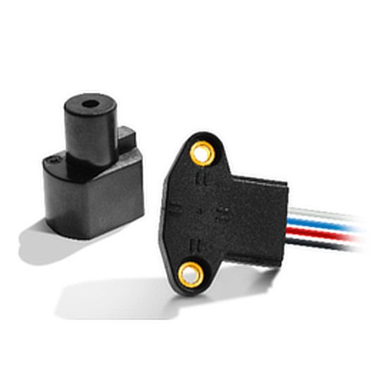
ZF, ANG Sensor

Angle and Linear Position Sensors

Angle and linear position sensors play a central role in many closed-loop automation applications. Both serve the same fundamental purpose, measuring where something is, but they do so in different dimensions.

Angle position sensors measure rotational movement, making them well suited to applications involving shafts, joints, valves and anything that pivots or rotates. Linear position sensors measure displacement along a straight axis, which is essential in motion control applications where an object moves between defined points.

Pressure Sensors

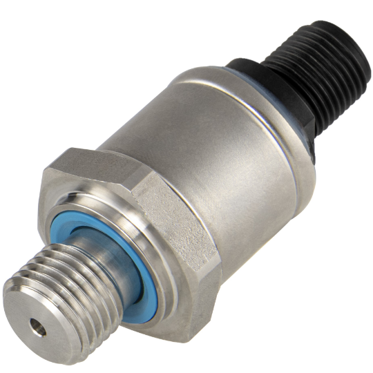
Pressure sensors serve a different but equally critical function. In systems that work with liquids, gases or steam, pressure measurement feeds directly into the control loop. It tells the system whether flow rates, containment levels and operating conditions are within specification.

In manufacturing, this might mean monitoring hydraulic pressure in a press or clamping mechanism. In pneumatic automation, it could be verifying that actuators are reaching their target pressure before triggering the next stage. In process environments, such as chemical processing or food production, it supports safe operation by identifying problems early, before they escalate. 

The breadth of applications that rely on pressure sensing reflects how fundamental it is to closed-loop control. Across automotive, aerospace, HVAC, healthcare and general industrial automation, accurate pressure data is one of the core inputs that allows a system to self-regulate rather than simply execute.

Choosing the Right Sensor for the Application

Sensor selection has a direct impact on how well a closed-loop system performs. A sensor that is not rated for its operating environment, or that lacks the resolution the control system requires, will introduce error into the feedback loop. This is regardless of how well everything else is specified.

Key considerations include:

  • The measurement range and resolution needed
  • The operating environment including temperature, ingress protection, vibration
  • The output signal type required by the controller
  • The expected service life relative to maintenance schedules.

Getting these decisions right at the specification stage avoids performance issues that are considerably harder and more expensive to resolve once a system is in production.

Supporting Your Automation Projects

Live Electronics supplies a range of sensors suited to closed-loop automation applications, including angle position sensors, linear position sensors and pressure sensors.

Our angle and linear position sensors from ZF use Hall Effect technology, which removes the need for physical contact between moving parts. This avoids the mechanical wear that affects traditional contact-based designs, maintaining accuracy over a far longer service life. In industrial environments where replacement or recalibration is costly and disruptive, that longevity is a reliability requirement as much as a performance one.

Alongside the components themselves, our technical team is available to support specification decisions, helping you identify the right sensor for your application before any purchase is made. If you are working on an automation project and want to discuss sensor selection, contact us directly. We aim to respond the same day and can provide a quote within 24 hours.

Designing Operator Interfaces for Industrial Control Panels

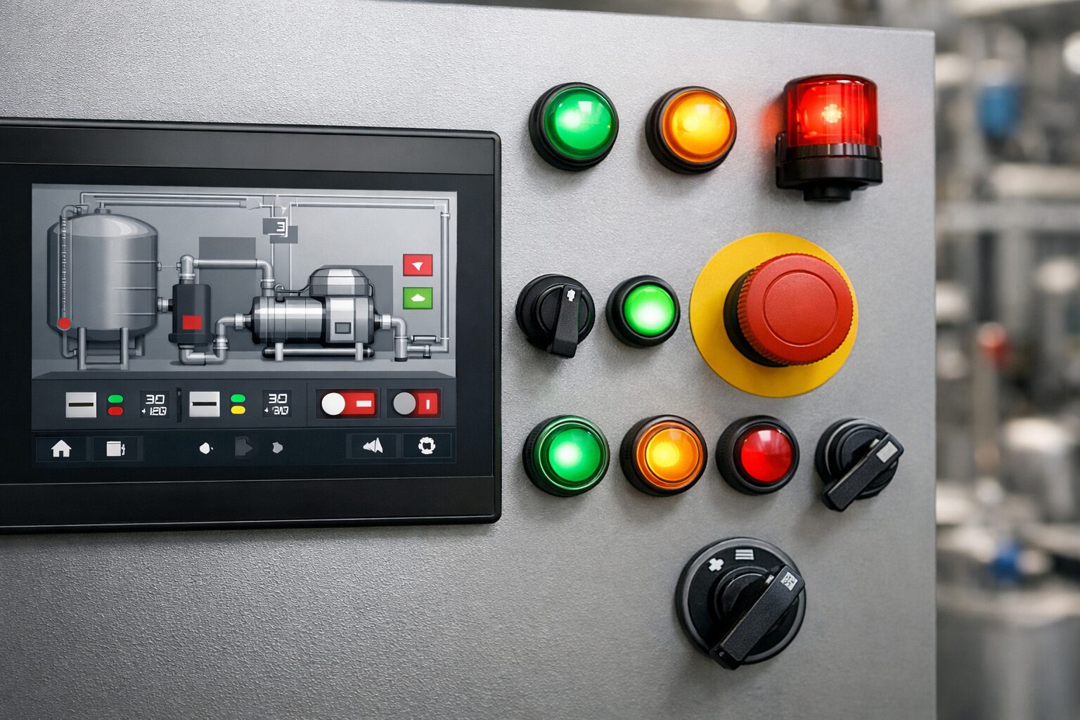
The efficiency and safety of an industrial environment depend heavily on the bridge between the human operator and the machine. A well-designed operator interface does more than just look professional; it reduces cognitive load, prevents user error, and ensures that critical information is accessible during high-pressure situations. When building or upgrading a control panel, the selection and placement of Human-Machine Interfaces (HMIs), switches, and indicators are the most vital decisions a designer can make. 

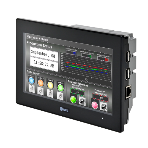
HMIs serve as the primary window into the operation, and their effectiveness relies on the design. It is best practice to avoid overly complex, complicated graphics which can distract the eye. Instead, using muted background colours like grey and saving bright colours exclusively for alarms or status changes, is much more effective. This ensures that an operator’s attention is instantly drawn to where it is needed most, when it is needed the most. Navigation should also be intuitive, with a shallow menu structure that allows users to access any critical screen within two or three touches. 

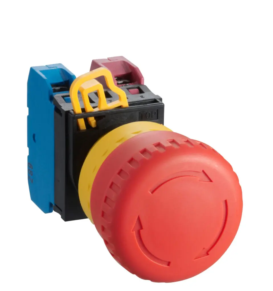
While digital screens provide deep data, physical switches and pushbuttons remain essential for tactile feedback and immediate action. Critical functions, such as emergency stops or common start/stop sequences, should always be assigned to high-quality physical switches. When selecting these components, considering the ergonomics and the environment is essential. For example, if operators wear gloves, larger pushbuttons are necessary to ensure the action is registered. Consistency in the layout of these switches across different panels in a facility can also significantly reduce the learning time for new staff. 

IDEC YW Emergency Stop

While digital screens provide deep data, physical switches and pushbuttons remain essential for tactile feedback and immediate action. Critical functions, such as emergency stops or common start/stop sequences, should always be assigned to high-quality physical switches. When selecting these components, considering the ergonomics and the environment is essential. For example, if operators wear gloves, larger pushbuttons are necessary to ensure the action is registered. Consistency in the layout of these switches across different panels in a facility can also significantly reduce the learning time for new staff. 

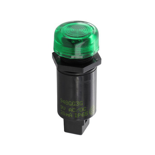
Sloan, Sloan AG, 948 Series, LED Indicator

Indicators and LED lights provide the “at-a-glance” status of the system. Effective use of colour is key again here: green typically signifies a safe or running state, red indicates a fault or stop, and amber suggests a warning or a transition. However, it is important to make sure the message of the indicator is clear for every operator, regardless of visual circumstances. For example, an LED indicator might be paired with a specific flashing pattern to denote a particular type of alert. 

Beyond the hardware components, the logic driving the system is what truly brings a control panel to life. At Live Electronics, we offer a specialised PLC Software Consultancy service, developed in partnership with our trusted experts at Tailored Engineering. With extensive experience in ladder logic programming, we can create customised PLC software tailored to meet the exact requirements of your automation systems. We work closely with you to understand your process, ensuring both the software and hardware are designed to function seamlessly within your operations, whether you are optimising an existing system or developing a new one from scratch. 

Ultimately, a successful operator interface is one that feels like a natural extension of the user’s intent. By combining high-quality physical components like robust switches and LED indicators with a compatible HMI and professional PLC programming, you create a system that is both productive and safe. Choosing the right components and expert advice at the design stage is an investment that pays off through reduced downtime and improved operational clarity for years to come. 

Hall Effect vs Potentiometer Controls: Which Is Right for Your Application?

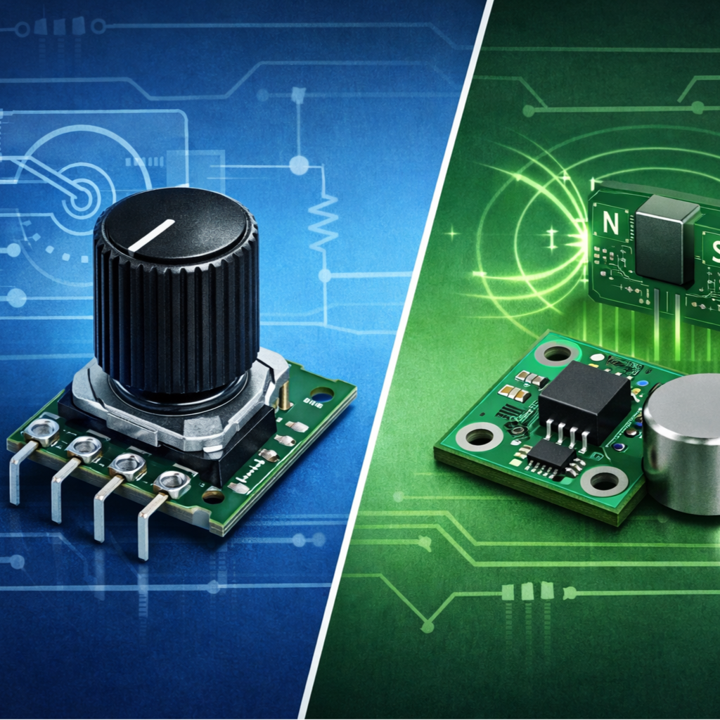
When designing a new system or upgrading an existing one, choosing the right control technology is crucial for optimal performance, longevity, and user experience. Two of the most common options for position sensing and control are Hall effect sensors and potentiometers. While both can achieve similar outcomes, their underlying principles, strengths, and weaknesses differ significantly. This blog post will delve into a technical comparison to help you determine which is best suited for your specific application. 

462 Subminiature Joystick

Potentiometers

Potentiometers have been a staple in electronics for decades, offering a simple and cost-effective method for variable resistance. 

How they work: 

A potentiometer consists of a resistive track and a wiper that moves along it. As the wiper’s position changes, the resistance between the wiper and one end of the track varies, thus changing the output voltage when a constant current is applied. 


Advantages: 

  • Simplicity and Cost: Potentiometers are generally less complex to manufacture and therefore more affordable, especially for basic applications. 
  • Direct Analogue Output: They provide a direct analogue voltage output proportional to position, which can be easy to interface with many circuits. 
  • No External Power (for passive use): In some basic resistive divider applications, they don’t require external power beyond the signal itself. 

Disadvantages: 

  • Wear and Tear: The mechanical contact between the wiper and the resistive track is prone to wear, leading to degradation in performance, increased noise, and ultimately, failure over time. This limits their lifespan, especially in applications with frequent movement. 
  • Environmental Sensitivity: Dust, moisture, and vibration can affect performance and accelerate wear. 
  • Limited Resolution and Accuracy: While good for many applications, the resolution can be limited by the physical construction and material consistency. 
  • Contact Bounce: The mechanical contact can sometimes lead to momentary signal instability. 

Ideal Applications:

Potentiometers are well suited for applications where cost is a primary concern and movement is infrequent. Examples include volume controls, basic calibration adjustments, and infrequent user input. 

Ruffy, Ruffy Controls, HE2 Joystick

Hall Effect Sensors

Hall effect sensors operate on a fundamentally different principle, offering significant advantages in demanding environments and high-reliability applications. 

How they work:

 A Hall effect sensor measures the change in a magnetic field. When a current flows through a semiconductor material (the Hall element) and a magnetic field is applied perpendicular to the current flow, a voltage difference (the Hall voltage) is generated across the semiconductor. The strength of this voltage is directly proportional to the strength of the magnetic field. In control applications, a magnet is typically attached to the moving part (e.g., a joystick lever or a rotary shaft), and the Hall sensor remains stationary, detecting the magnet’s position. 

Advantages: 

  • Non-Contact Sensing: This is the most significant advantage. Because there is no mechanical contact between the sensing element and the moving part, there is no wear and tear. This translates to: 
  • Virtually Unlimited Lifespan: Hall effect sensors can last for millions of cycles without degradation, making them ideal for high-use applications. 
  • Improved Reliability: Less prone to mechanical failure. 
  • Reduced Noise: No contact bounce or noise associated with physical wear. 
  • Environmental Robustness: Being sealed and non-contact, they are highly resistant to dust, dirt, moisture, vibration, and extreme temperatures, making them suitable for harsh industrial or outdoor environments. 
  • High Resolution and Accuracy: Hall effect sensors can offer very high precision and repeatability, providing smooth and accurate control. 
  • Solid-State Design: Their solid-state nature makes them durable and robust. 

Disadvantages: 

  • Higher Cost: Generally, more expensive than potentiometers, especially for basic sensing. 
  • Requires External Power: Hall effect sensors are active devices and require a power supply to operate. 
  • Magnetic Interference: Can be susceptible to strong external magnetic fields if not properly shielded or designed. 

Ideal Applications: 

Hall effect sensors excel in applications requiring high reliability, long lifespan, precision, and operation in harsh environments. Perfect for industrial controls, automotive vehicles, medical equipment, and gaming where smooth, precise, and durable control is paramount. 

Making the Final Choice

The decision between Hall effect and potentiometer controls ultimately comes down to your application’s specific environment and duty cycle. 

If you are working on a cost-sensitive project where the control will be used indoors and infrequently, a potentiometer remains a highly effective and simple solution. However, for industrial applications, outdoor machinery, or any system where downtime is not an option, the Hall effect is the superior choice. Its non-contact nature eliminates the physical wear that plagues potentiometers, providing a “fit and forget” solution that maintains precision over millions of cycles. 

By investing in Hall effect technology, you are choosing long-term reliability and reducing future maintenance costs, ensuring your equipment performs accurately, every time. 

Ready to Upgrade Your Control Interface?

At Live Electronics, we stock a comprehensive range of high-performance control solutions tailored to your technical requirements. We stock a comprehensive range of high-performance Hall Effect joysticks for demanding environments, as well as versatile potentiometer joysticks.  

Contact our technical sales team today to discuss your project requirements or to request a datasheet for our latest control components. 

Choosing the Right Industrial Components for Reliable Automation Systems

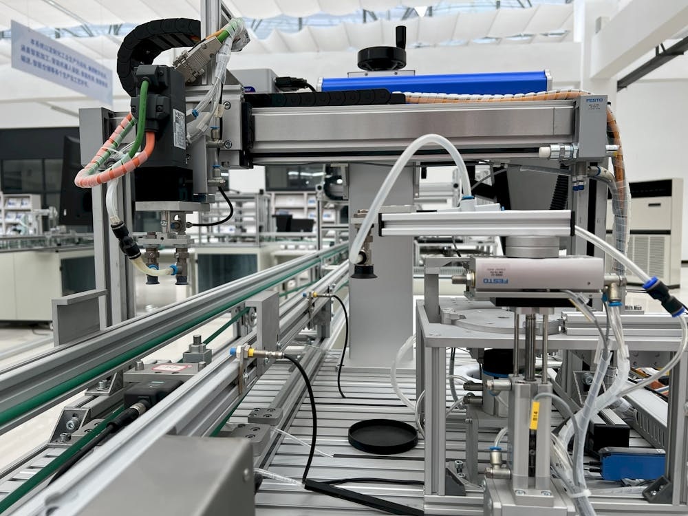
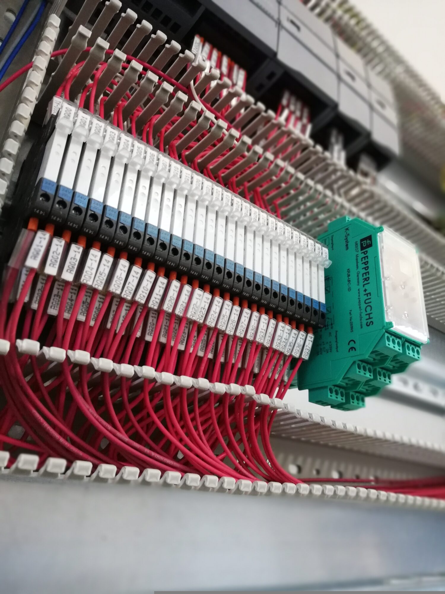
We know that when a production line stops, the pressure mounts instantly. Between the hit to your bottom line and the scramble to meet deadlines, downtime is the ultimate enemy. Building a high-performance system requires more than just smart code; it requires dependable and rugged components that can bridge the gap between digital theory and mechanical reality without risking failing. 

As a distributor of electronic componentswe’ve seen how choosing the right components from the start prevents the “maintenance headaches” in the future. Here is a breakdown of the key component categories essential for building reliable automation systems. 

1. The Brains: Control Systems & PLCs

At the heart of every automation production is the controller. It processes inputs from the environment and executes commands to the machinery. 

  • Programmable Logic Controllers (PLCs): These are the workhorses of the industry. When selecting a PLC, reliability in harsh environments, handling heat, vibration, and electrical noise, is necessary. 
  • Our Focus: We supply a range of high-performance PLCs designed for scalability, ensuring that as your automation needs grow, your control system doesn’t become a bottleneck. 

2. The Senses: Industrial Sensors

An automation system is only as good as the data it receives. If a sensor fails or provides inaccurate readings, the entire system can fail or worse, operate unsafely. 

  • Precision & Durability: Whether you are measuring distance, pressure, or presence, the sensor must be rated for your specific environment (IP ratings for moisture/dust). 
  • Our Focus: We offer a comprehensive suite of sensor solutions tailored to your environment., ensuring your system “sees” and “feels” its environment with 100% accuracy. 


3. The Interface: Joysticks and Switches

Human-Machine Interface (HMI) isn’t just about touchscreens; it’s about the tactile hardware that allows operators to intervene or guide heavy machinery with precision. 

  • Joysticks: For applications involving material handling or robotics, high-duty cycle joysticks are essential. They provide the ergonomic reliability needed for long shifts and precise movements. 
  • Switches: From emergency stops (E-Stops) to simple toggle functions, switches must offer positive tactile feedback and high electrical endurance. 
  • Our Focus: We provide industrial-grade joysticks and robust switches that are built to withstand millions of cycles in demanding settings. 

4. The Nervous System: Connectors and Cables

Often overlooked, connectors are the leading cause of intermittent system failures. A loose connection or a corroded terminal can shut down a major facility. 

  • Secure Interconnects: In automation, vibration is a constant. Using locking connectors is non-negotiable for long-term reliability. 
  • Our Focus: We emphasise high-integrity connectors that ensure power and data flow uninterrupted, even in high-vibration or high-interference (EMI) zones. 

Why Component Selection Matters

Building for reliability means looking beyond the datasheet. It’s about understanding how these components interact under pressure. By sourcing quality PLCs, sensors, and human interface tools, you reduce the Total Cost of Ownership (TCO) by slashing downtime. 

Ready to specify your next project? At Live Electronics, we don’t just move boxes; we help you find the specific part that fits your environmental and technical requirements. 

Greener Electronics: How Energy Efficient Components Are Driving Sustainable Design

As global industries push towards sustainability, electronics engineers are under increasing pressure to design devices that are not only high-performing but also energy-efficient and environmentally friendly. From industrial automation to consumer electronics, the choice of components now plays a crucial role in meeting both regulatory requirements and environmental goals. 

Why Energy Efficiency Matters in Electronics

Power consumption isn’t just about energy bills, it’s about: 

  • Thermal management: Less wasted energy reduces heat, extending component lifespan. 
  • Regulatory compliance: Standards like RoHS, REACH, and UL require manufacturers to minimise environmental impact. 
  • System reliability: Lower energy consumption often translates to fewer failures and reduced maintenance. 

Selecting the right switches, relays, and connectors can drastically reduce energy losses, especially in high density circuits or always on systems like IoT devices and industrial controllers.

Innovations in Energy Efficient Components

Component manufacturers are rising to the challenge with innovations like: 

  • Low-loss power relays that minimise heat generation. 
  • High-efficiency connectors designed to reduce resistance and leakage current. 
  • Smart sensors with ultra-low standby power, ideal for battery-powered or remote IoT applications. 

For example, new solid-state relays and connectors can reduce power loss by up to 30% compared to traditional alternatives, improving both device efficiency and longevity.

How Live Electronics Can Help

At Live Electronics, we provide a wide range of high-efficiency, low-loss components suitable for various applications. Our product range includes: 

  • Energy-efficient connectors and switches 
  • Low-power relays and solid-state devices 
  • Components that comply with global environmental standards 

Choosing the right parts today can make a measurable difference in both device performance and environmental impact tomorrow. Sustainability doesn’t have to come at the cost of performance; the right components make it achievable. 

Choosing Between Solder, Crimp and Screw Terminations

When working on any electrical or electronic project, a critical decision is how to connect wires to components, terminals, or other connectors. The quality of these terminations directly impacts the reliability, performance, and safety of your circuit. The three most common methods are soldercrimp, and screw terminations. Each has its own strengths and weaknesses, making it ideal for specific applications. 

Solder Terminations

Soldering involves melting a metal alloy (solder) to create a metallic bond between the wire and the terminal. The solder flows into the junction, cooling to form a strong, permanent, and electrically conductive connection. 

Advantages: 

  • Excellent Electrical Conductivity: The connection is highly stable and has very low resistance. 
  • Permanent: Resistant to vibration and corrosion, making it extremely reliable. 
  • Small Form Factor: Ideal for high-density circuits, such as printed circuit boards (PCBs). 

Disadvantages: 

  • Requires Skill: Poor soldering (cold joints or solder bridges) leads to unreliable connections. 
  • Time-Consuming: Each joint must be heated and cooled individually. This can be done automatically with a machine, however this does involve extra costs. 
  • Not Easily Reworkable: Removing solder is a delicate process, and excessive heat can damage components. 

Crimp Terminations

Crimping is a method where a barrel-shaped terminal (often a connector, lug, or ferrule) is mechanically compressed around the wire conductor, causing the metal crimp to bend into the wires and form a friction bond.  

Advantages: 

  • Fast and Repeatable: Once the correct crimp tool is set, the process is extremely quick and consistent. 
  • Mechanically Strong: A well-executed crimp offers excellent pull-out strength and vibration resistance. 
  • No Heat Involved: Safe for heat-sensitive components and eliminates the risk of heat damage to the insulation. 

Disadvantages: 

  • Tool Dependent: Requires the correct crimping tool for the specific terminal and wire gauge. Using the wrong tool results in a poor connection. 
  • Visual Inspection Difficult: It can be hard to tell a good crimp from a bad one without destructive testing. 
  • Material Specific: Terminals and lugs must be compatible with the wire material. 


Screw Terminations

Screw terminals rely on mechanical pressure. The wire, stripped or fitted with a ferrule or ring/fork terminal, is placed under the head of a screw (or a clamping plate) which is then tightened to hold the conductor securely. 

Advantages: 

  • Easily Reworkable: Connections can be quickly loosened and re-tightened, making them ideal for testing, prototyping, and maintenance. 
  • Simple Tooling: Requires only a standard screwdriver, making them accessible. 
  • Handles Large Gauges: Often the best choice for connecting heavy-gauge power wires. 

Disadvantages: 

  • Vibration Loosening: Mechanical connections can loosen over time, especially in high-vibration settings, leading to high resistance or intermittent faults. 
  • Wire Damage: Overtightening can shear the screw or damage the wire strands. 
  • Air Exposure: The connection is not fully sealed, allowing the conductor to oxidize over time, increasing resistance. 

The right choice isn’t just about what’s strongest or easiest, it’s about matching the termination method to the environment, current/voltage requirements, service needs, and expected lifespan of the project. A careful assessment of these factors ensures a reliable and professional result every time. 

Relays: What’s the Difference?

When controlling circuits, relays are the unsung heroes of electronic design. From automotive systems to industrial automation, these compact devices provide isolation, switching, and protection, ensuring that low power control signals can safely operate high power loads. But not all relays are the same. In this post, we’ll explore the key types of relays, how they work, and which one is right for your next project. 

What is a relay?

A relay can be an electromechanical or solid-state switch that uses a small electrical signal to control a larger current. Traditionally, a magnetic coil activated a mechanical contact which turned a circuit on or off. Modern designs, however, have evolved into a variety of specialised technologies to meet different performance and reliability needs. 

The Two Main Families: Electromechanical vs. Solid-State

1. Electromechanical Relays (EMR) 

How they work:
Electromechanical relays use a physical coil and armature to open or close contacts. When current flows through the coil, it creates a magnetic field. This field attracts a movable armature, which physically opens or closes a set of electrical contacts. 

Best for: Applications where a complete electrical isolation is required and where switching speed and frequency are low, like industrial control panels, HVAC systems, and power distribution. 

AdvantagesDisadvantages
Excellent isolation between control and load circuits Slower switching speed  
Cost-effective and easy to use  Mechanical wear and tear  
Suitable for AC or DC switching Produces arc/noise

2. Solid State Relays (SSR) 

How they work:
Solid State Relays use semiconductor components (like transistors, MOSFETs, or TRIACs) to perform the switching function, with no moving parts. An input signal, usually isolated by an optocoupler, controls the semiconductor device, allowing or blocking the flow of current. 

A specialised type of SSR’s, Safety Relays, are designed for machine safety and emergency stop circuits, where reliability and rapid fault detection are critical. They use semiconductor technology to provide wear-free, high-speed switching while meeting safety standards. 

Best for: Applications requiring fast, frequent, and silent switching, or where mechanical wear must be avoided, such as automation systems, test equipment, high-speed industrial machinery, and environments with vibration or shock. 

AdvantagesDisadvantages
Fast switching speed Higher "on" resistance 
No mechanical wear  Power dissipation 
Silent operation Current leakage
No contact bounce/arcingMore expensive 

Choosing the correct relay

When selecting a relay, several critical specifications dictate which component is right for your design: 

  • Load Type: AC, DC, resistive, or inductive 
  • Switching Current and Voltage: Ensure contacts can handle the load safely 
  • Switching Speed: SSRs are faster; EMRs suit slower, high-current applications 
  • Environmental Factors: Vibration, temperature, and contamination can affect performance 
  • Lifetime Requirements: SSRs excel in high-duty cycles; EMRs offer robust simplicity 

Relays may perform a simple function; switching, but the variety of technologies available makes choosing the right one essential to system performance and reliability. Understanding the differences between the two most common relays ensures you get the best balance of durability, speed, and cost for your design. 

Need Help? Contact Live Electronics!

The technology of modern switching demands speed, durability, and reliability. That’s why at Live Electronics, we’ve specialised in the future of switching: Solid-State Relays (SSRs). We offer a comprehensive range of cutting-edge SSRs from industry-leading manufacturers, ensuring you get the fastest, longest-lasting solution for your needs. 

Contact our expert team today, and we’ll help you pinpoint the perfect SSR with the right heat dissipation, load rating, and ultrafast switching characteristics to ensure your high-frequency circuit functions reliably and efficiently. 

Piezo Technology: What It Is and How It Works

Everyday life is full of tiny technologies we rarely notice, yet we rely on them constantly. Piezo technology is one of those hidden forces, making your watch keep time, your phone vibrate, and even helping cars run more efficiently. At its core, it’s all about turning pressure into electricity and electricity into motion, a principle that has quietly powered innovation for over a century. 

What Is Piezo Technology?

The term piezo comes from the Greek word piezein, meaning “to press” or “squeeze.” Piezo technology is based on the piezoelectric effect, a unique property of certain crystals and ceramics that generate an electrical charge when mechanically stressed. 

In simple terms: 

  • If you squeeze or bend a piezo material, it creates electricity. 
  • Conversely, if you apply electricity to it, the material changes shape (expands, contracts, or vibrates). 

This two-way capability makes piezo materials incredibly versatile, enabling both sensing and actuation. 

How Does It Work?

At the heart of piezo technology is the piezoelectric effect, first discovered in the late 19th century by Jacques and Pierre Curie. Here’s how it works in practice: 

  1. The Direct Effect (Generating Electricity):
    When you apply pressure, vibrations, or mechanical force to a piezo material, the internal crystal lattice gets deformed. This deformation shifts the electric charges within the structure, producing a measurable voltage across the material. 

Example: In a barbecue lighter, pressing the button compresses a piezo crystal, which releases a spark. 

  1. The Inverse Effect (Movement from Electricity):
    When an electric voltage is applied to the piezo material, its shape changes slightly. Though the movement is tiny (microns or less), it’s fast, precise, and powerful enough to control high-tech devices. 

Example: In medical ultrasound scanners, piezo crystals vibrate when energized, creating sound waves that bounce back to form images of internal organs. 

Applications of Piezo Technology

A major advantage of piezoelectric materials is their adaptability. Some key applications include: 

  • Medical Devices: Ultrasound imaging, surgical tools, and drug delivery systems. 
  • Consumer Electronics: Microphones, speakers, vibration motors, and sensors in touch devices. 
  • Automotive: Fuel injectors, tire pressure sensors, and knock sensors in engines. 
  • Industrial: Precision actuators, flow monitors, and vibration sensors in machinery. 
  • Energy Harvesting: Small-scale power generation from vibrations, footsteps, or environmental movements. 


Piezo technology might not be as visible as smartphones or computers, but it plays a crucial role in making many modern devices smarter, smaller, and more efficient. Its ability to convert mechanical energy into electrical energy (and vice versa) has opened up possibilities across healthcare, automotive, consumer electronics, and even renewable energy. 

As research continues, we’ll likely see piezo applications expand into even more innovative fields — perhaps powering future sensors, wearable devices, or self-charging systems. In short, piezo technology is proof that sometimes the smallest movements can have the biggest impact. 

What is a HDMI Connector?

As an electronic component distributor, we understand the importance of reliable connectivity solutions across all industries. HDMI (High-Definition Multimedia Interface) connectors are a key component in ensuring high quality transmission of digital video and audio signals. Commonly used in consumer electronics, industrial equipment and professional AV systems, HDMI connectors offer a simple, all-in-one solution for connecting displays and devices.

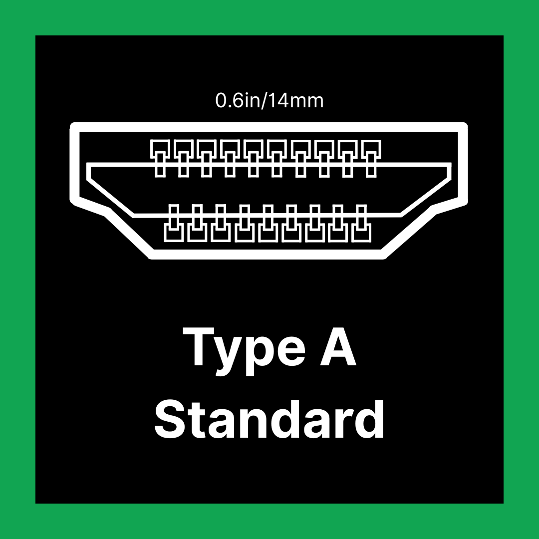
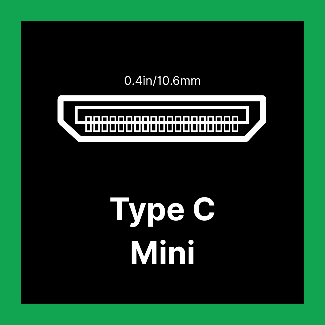
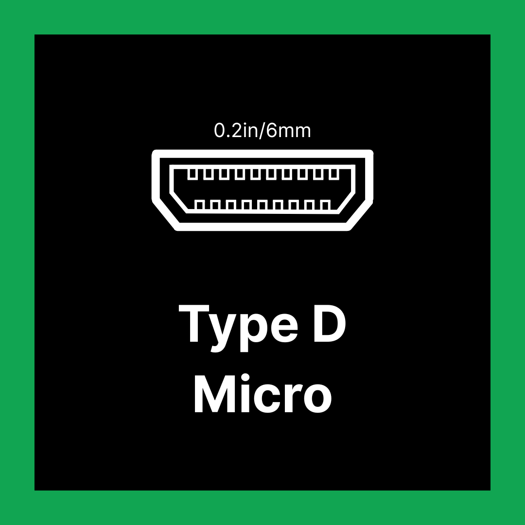
There are five types of HDMI connectors; A, B, C, D and E, these types are based on the size and shape required. However, in this post, we will explore the 3 predominant types of HDMI connectors available and highlight their key features and benefits. The most used HDMI connectors today are Type A (Standard), Type C (Mini), and Type D (Micro). Some of these have expanded to include more support with Version 1.0 supporting 1080P video and 8-chanel audio to the newly released (as of January 2025) version 2.2 capable of support for up to 16K resolution. Although the physical design of the Type A connector, with its 19-pin layout, has remained the same, its capabilities have greatly improved for present-day needs.

HDMI Type A (1.0 - 2.2) (Standard)

Let’s start with the most widely used HDMI connector; Type A, also known as the standard HDMI, which was created in 2002. The initial goal was to create a single digital interface for both audio and video, replacing multiple analogue connections offering better quality and convenience. This 19-pin connector is the largest among the HDMI types and is commonly found on a wide range of devices. It’s typically used to connect source devices such as set-top boxes, gaming consoles, Blu-ray players, and computers to display devices like TVs, projectors and monitors. Type A HDMI supports digital transmission of both high-definition video and multi-channel audio, accommodating resolutions ranging from 1080P to 16k @ 60Hz. Due to its versatility and widespread compatibility, the standard HDMI connector (Type A) is the most prevalent of all HDMI types, featured across nearly all brands of TVs, computer monitors, streaming devices and desktop computers.

HDMI Type C (1.3-2.1) (Mini)

Type C (Mini) HDMI connectors made in 2006 are compact digital interfaces designed to deliver high-definition audio and video signals from portable devices to larger display systems. This smaller form factor allowed for the integration of high-definition multimedia interfaces into more compact devices. Like standard HDMI connectors, Mini HDMI also uses a 19-pin configuration and supports high-definition formats, including 10K, ensuring excellent audio and video quality. Despite their smaller size, Mini HDMI connectors offer the full functionality of standard HDMI ports. Commonly found on DSLR cameras, camcorders, tablets and some laptops, they provide a convenient solution for connecting compact electronics to TVs, monitors and projectors. HDMI Type C (Mini HDMI) connectors can technically support versions higher than 1.4 however it is rare to have these supporting HDMI 2.0 or higher.

HDMI Type D (1.4b) (Micro)

Type D (Micro) HDMI connectors take miniaturisation a step further, delivering a highly compact yet fully functional solution for transmitting high-definition audio and video from ultra-portable devices. It was introduced to meet the growing demand for smaller connectors in devices like smartphones and cameras in 2009. Despite being even smaller than the Mini HDMI, Micro HDMI maintains the same 19-pin configuration and supports the full range of HDMI features, including 1080p to 4K resolution. It is commonly found on slim digital cameras, smartphones and compact tablets, where there isn’t as much room for larger ports. A typical Micro HDMI cable features a Micro connector on one end and a standard Type A connector on the other, enabling seamless connection to TVs, monitors and projectors. This makes it an ideal choice for users who need powerful multimedia capabilities in a small space.

The transition from HDMI to USB-C:

Many new devices are shifting from Micro HDMI to USB-C, driven by the demand for slimmer designs and more versatile connectivity. USB-C’s compact size and ability to handle video, audio, data, and power through a single port make it an attractive alternative for manufacturers. While adapter cables are available to connect USB-C to HDMI displays, they typically operate using HDMI 1.4b standards limiting output to 4K at 30Hz. For users requiring higher resolutions or refresh rates, such as 4K at 60Hz or 8K video, only HDMI version 2.1 or higher can meet those demands. Though USB-C offers impressive multifunctionality, it comes with trade-offs in video performance when compared to the latest HDMI standards.

How to know which HDMI to use:

Overall, knowing which HDMI cable and connector to use depends on both identifying the cable and understanding your device requirements. You can determine the cable type by checking the text printed on the cable itself, or examining the original packaging, these often indicate the HDMI version. Once identified, match the cable to your needs; for standard 1080p displays, a High-Speed HDMI cable is typically enough. However, if you’re working with 4K or higher resolutions, faster refresh rates or features like Ethernet or Audio Return Channel, a Premium High Speed or Ultra High-Speed HDMI cable is necessary such as Type A 2.2. By considering both the cable’s specifications and your equipment’s requirements, you can ensure optimal performance and compatibility.

At Live Electronics, we are here to help you make the right choice. We carry a range of HDMI connectors to ensure compatibility and performance. Whether you’re outfitting a high-performance vehicle or building a cutting-edge production setup, Live Electronics is your trusted source for reliable, industry-grade HDMI solutions.

How the Industrial Internet of Things (IIoT) Is Transforming Industry

As technology continues to advance at a rapid pace, one of the most transformative innovations reshaping traditional industries is the Industrial Internet of Things (IIoT). While IoT has become familiar in our homes through smart thermostats and wearable devices, IIoT extends this connected intelligence to the industrial sector, where the challenges are greater, and the rewards even more significant.

What is IIoT?

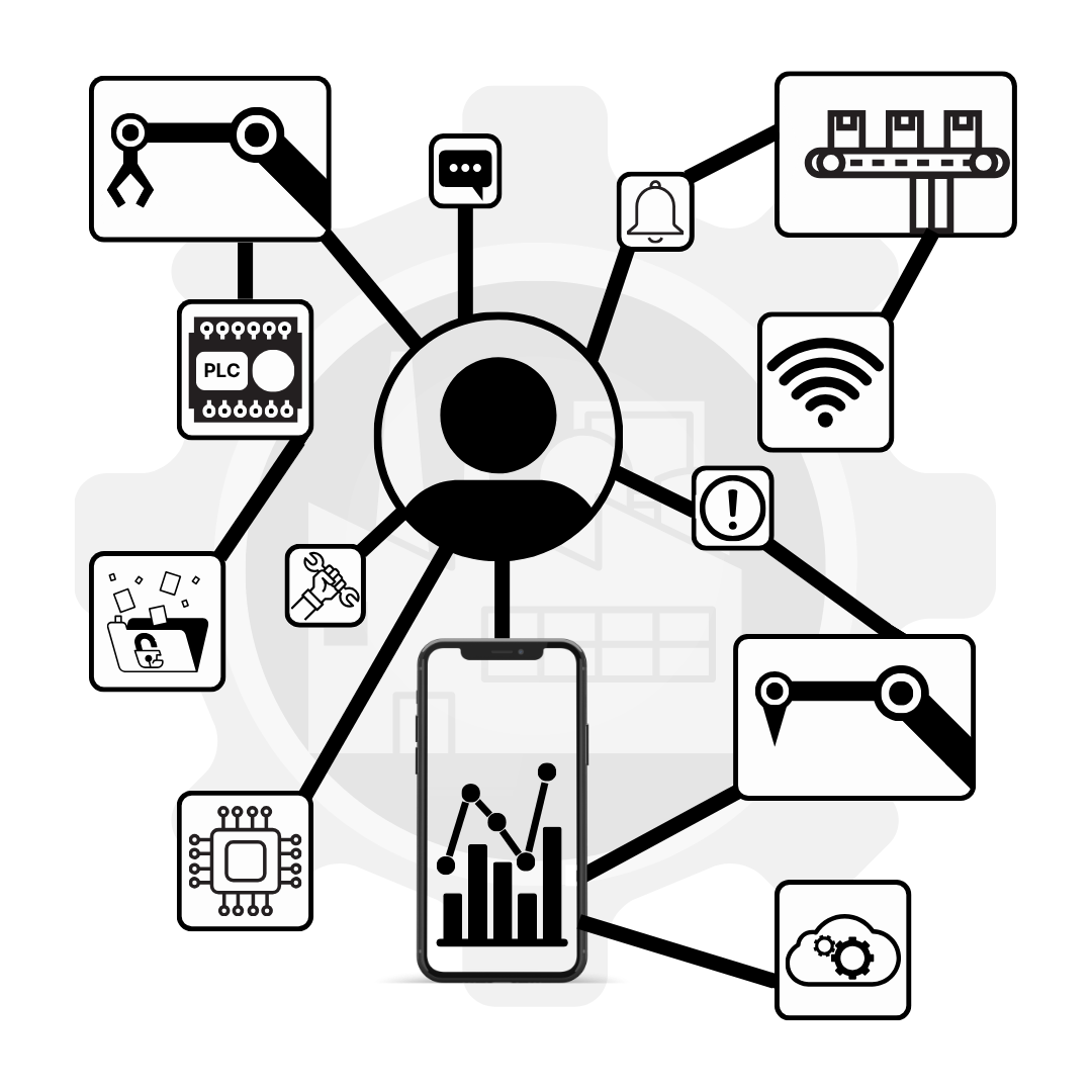
The Industrial Internet of Things refers to the network of interconnected devices, sensors, and systems used in industrial settings like manufacturing, energy, agriculture, logistics, and utilities. These devices collect and exchange data, enabling smarter decision-making, automation, and predictive insights.

IIoT has played a central role in powering Industry 4.0, the fourth industrial revolution, defined by smart, connected manufacturing systems that are highly efficient and responsive.

Key Components of IIoT in Manufacturing

Implementing IIoT in manufacturing relies on a few essential building blocks that enable smarter, more connected operations:

  1. Smart Sensors

In manufacturing, smart sensors are embedded in machinery, conveyors, robotic arms. These collect real-time data from machines and the environment to help monitor performance, detect issues, and ensure product quality.

  1. Edge Devices

Edge devices, such as PLCs, process data directly on the factory floor, enabling real-time responses, predictive maintenance, and faster decision-making without relying on.

  1. Connectivity

Manufacturing environments require reliable and fast connectivity to enable communication between machines and systems, ensuring a seamless data flow and coordination across the factory. These include Ethernet, Wi-Fi and Modbus.

  1. Cloud and Analytics

Cloud platforms help manufacturers gain insights from operational data by enabling monitoring and performance tracking, acting as a central hub that connects systems and supports smarter, data-driven decisions.

  1. Cybersecurity

Given the critical nature of industrial systems, robust security frameworks are essential to prevent disruptions and data breaches.

The Future of IIoT

As IIoT continues to evolve, it will continue to shape the future of industrial strategy, driving new levels of productivity, agility, and cost-efficiency. Advancements in AI, machine learning, and 5G connectivity will unlock even greater capabilities. Smart factories will become more autonomous, adaptable, and efficient, able to respond in real time to changing market demands.